Simplex 4099-5203, 4099-5204 MX Technology Addressable Devices – Addressable Callpoints, Available for Indoor or Outdoor

File Preview
Click below to download for free
Click below to download for free
File Data
| Name | simplex-4099-5203-4099-5204-mx-technology-addressable-devices-addressable-callpoints-available-for-indoor-or-outdoor-4980572613.pdf |
|---|---|
| Type | |
| Size | 726.97 KB |
| Downloads |
Text Preview
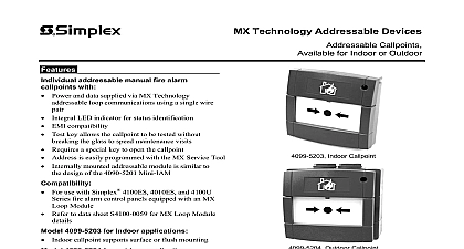
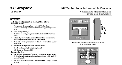
Technology Addressable Devices Callpoints for Indoor or Outdoor addressable manual fire alarm with Power and data supplied via MX Technology loop communications using a single wire LED indicator for status identification EMI compatibility Test key allows the callpoint to be tested without the glass to speed maintenance visits Requires a special key to open the callpoint Address is easily programmed with the MX Service Tool mounted addressable module is similar to design of the 4090 5201 Mini IAM For use with Simplex 4100ES 4010ES and 4100U fire alarm control panels equipped with an MX Module Refer to data sheet S4100 0059 for MX Loop Module callpoint supports surface or flush mounting 4099 5203 for indoor applications 4099 5204 for outdoor applications Rated as IP67 for external applications Outdoor callpoints are for surface mounting manual callpoints with compact module are easily installed to satisfy applications An integral addressable module status and communicates changes to the control panel via MX Loop communications are signaled by breaking a glass element which a switch and is indicated by an LED indicator Selection Loop Addressable Manual Callpoints MX Loop addressable indoor Loop addressable outdoor includes surface box Surface mount backbox for indoor callpoints Callpoint replacement glass package of 10 mm deep 1 Indoor Callpoint Outdoor Callpoint Specifications and Loop 1 address per callpoint Means Connections mA in standby mA in alarm with MX Service Tool blocks for wire size to 14 AWG 0.5 to 2.5 mm2 RAL3001 4099 5203 Indoor Callpoint Temperature Range Protection housing semi flush mount 4099 5204 Outdoor Callpoint Temperature Protection with box to 95 RH non condensing H x 3 W x 1 1 D mm x 89 mm x 28 mm H x 3 13 W x 2 D mm x 97.5 mm x 73 mm F to 131 F 10 C to 55 C F to 158 F 25 C to 70 C 11 2011 Application Reference to NFPA 72 the National Fire Alarm and Signaling and all applicable local codes for complete for manual callpoints The following the basic requirements Callpoints shall be located in the normal path of exit distributed in the protected area such that they unobstructed and readily accessible Mounting shall be with the operable part not less than ft 1.1 m and not more than 4 ft 1.37 m floor level At least one callpoint shall be provided on each floor callpoints shall be provided to obtain a distance not more than 200 ft 61m to the callpoint from any part of the building When manual callpoint coverage appears limited in way additional callpoints should be installed Operation of the callpoint requires the glass element to broken A protective plastic coating on the glass operator injury and inhibits the release of glass A hammer is not required Completing the operates a micro switch whose condition is back to the control panel reset requires the use of a special key with the callpoint to remove the front cover allows the glass element to be replaced testing is performed by inserting the key into the bottom of the housing and pulling down releases the bottom of the housing and break glass To reset the callpoint the bottom of the housing pushed upwards until it locks in position Mounting Reference Indoor Callpoint Mounting Options Outdoor Mounting mm mm mm mm Mount with Surface Box mm mm mm 25 mm Mount with Box and Shallow Box in Wall mm 73 mm Mount with Box SIMPLEX and the product names listed in this material are marks and or registered marks Unauthorized use is strictly prohibited NFPA 72 and National Fire Alarm are trademarks of the National Fire Protection Association NFPA 2011 Tyco Fire Protection Products All rights reserved All specifications and other information shown were current as of document revision date and are subject to change without notice Fire Protection Products Westminster MA 01441 0001 USA 11 2011