Simplex 4099-9801C IDNet 2-Stage Station IAM Installation Instructions

File Preview
Click below to download for free
Click below to download for free
File Data
| Name | simplex-4099-9801c-idnet-2-stage-station-iam-installation-instructions-1297865430.pdf |
|---|---|
| Type | |
| Size | 1004.04 KB |
| Downloads |
Text Preview
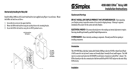
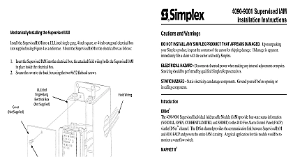
installing the 2 Stage Station all electrical connections have been made install the 2 Stage Station IAM into a electrical box not behind the Manual Station using Figure 4 as a reference Refer to the 2099 Series Non Coded Alarm Stations Installation and Operating Instructions 574 656 for information on other mounting Mount the 2 Stage Station IAM to the electrical box as follows surface mounting use a 2975 9178 red steel back box or a 2975 9022 aluminum back box Do not a box with a depth less than 2 3 16 inches 5.55 centimeters semi flush mounting use a standard 4 inch 10.16 centimeters square back box with a minimum depth 2 1 8 inches 5.39 centimeters Fit the back box with a 3 4 inch 1.9 centimeters deep single gang cover set flush DO NOT RECESS or protruding 1 16 inch 16 centimeter from the wall surface the 2 Stage Station IAM inside the electrical box in a position that allows the manual station room to be mounted onto the electrical box The attached field wiring holds the 2 Stage IAM in place inside the electrical box Secure the manual station to the back box IDNet 2 Stage Station IAM Instructions and Warnings NOT INSTALL ANY SIMPLEX PRODUCT THAT APPEARS DAMAGED Upon unpacking Simplex product inspect the contents of the carton for shipping damage If damage is apparent file a claim with the carrier and notify Simplex HAZARD Disconnect electrical power when making any internal adjustments or repairs should be performed by qualified Simplex Representatives HAZARD Static electricity can damage components Ground yourself before opening or components 4099 9801C 2 Stage Station Individual Addressable Module IAM provides addressability to type hardwired stations The four device states NORMAL OPEN CURRENT LIMITED SHORT are communicated to the 4010 Fire Alarm Control Panel FACP via the IDNet channel for both General Alarm and Pre Signal Alarm are supervised by the IAM The IDNet channel the communication link between the IAM and the 4010 FACP and powers the entire IAM circuitry Station IAM installation consists of following Setting the 2 Stage Station IAMs address Making electrical connections to the 2 Stage Assembly IAM and to the IDNet channel Mechanically installing the 2 Stage Station IAM Switch Re sealable Label View View The LED flashes approximately once every three to indicate valid communications with the FACP 1 2 Stage Station IAM Installation 4 2 Stage Station IAM Back Box Installation D 2000 Simplex Time Recorder Co Westminster MA 01441 0001 USA 2000 Simplex International Time Equipment Co Ltd Mississauga Ontario L4V 1H3 Canada specifications and other information shown were current as of publication and are subject to change without notice is a trademark of Simplex Time Recorder Company following an 8 digit Product ID number denotes ULC listed product D the 2 Stage Station IAMs Address 2 Stage Station IAM has a unique address 1 through 250 The address of the IAM is set by an eight dip switch Figure 1 DIP switch position 1 is the least significant bit LSB and position 8 is the most bit MSB Set the IAMs address using Figure 2 as reference Use a small screwdriver or pen to set switches The device address for the 2 Stage Station IAM should be written on the re sealable label this provides an aid in troubleshooting the system DIP switch in position is while DIP switch in position is IS SHOWN SET AT ADDRESS 7 ON OFF SWITCHES 5 THRU 8 1000 0100 1100 0010 1010 0110 1110 0001 1001 0101 1101 0011 1011 0111 1111 128 144 160 176 192 208 224 240 129 145 161 177 193 209 225 241 130 146 162 178 194 210 226 242 131 147 163 179 195 211 227 243 116 132 148 164 180 196 212 228 244 117 133 149 165 181 197 213 229 245 118 134 150 166 182 198 214 230 246 119 135 151 167 183 199 215 231 247 120 136 152 168 184 200 216 232 248 121 137 153 169 185 201 217 233 249 122 138 154 170 186 202 218 234 250 123 139 155 171 187 203 219 235 124 140 156 172 188 204 220 236 125 141 157 173 189 205 221 237 126 142 158 174 190 206 222 238 127 143 159 175 191 207 223 239 2 2 Stage Station IAM Address Chart the 2 Stage Station IAM to the 4010 panel using the 4010 Fire Alarm PC Programmer Installation Programming Instructions 574 187 and 4010 Fire Alarm Front Panel Installing Operating and Instructions 574 052 Refer to 4010 panel label 526 444 for appropriate revision of the to be used Electrical Connections to the 2 Stage Station IAM IDNet channel connects to the 2 Stage Station IAM via terminals 1 and 2 The manual station connects the 2 Stage Station IAM via terminals 3 and 4 Terminal connections are illustrated in Figure 3 Do not loop wire under terminals Break wire runs to provide supervision to device K 1 2 W K 1 2 W STATION 2099 9107C 9108C 9759C When connecting two wires to one terminal position one wire on each side of the terminal screw allowable run from 4010 FACP to farthest device not to exceed 2500 feet Maximum wire including all T Taps from 4010 FACP is 10000 feet IDNet wiring is supervised and Maximum wire length is 500 feet 18 AWG Refer to Field Wiring Diagram 842 073 for further information Refer to 4010 panel label 526 444 appropriate revision of the Field Wiring Diagram to be used 3 2 Stage Station IAM Connections