Simplex 4100-0121 - 2120-0243 Modem Bridge Interface Card

File Preview
Click below to download for free
Click below to download for free
File Data
| Name | simplex-4100-0121-2120-0243-modem-bridge-interface-card-1427659083.pdf |
|---|---|
| Type | |
| Size | 924.37 KB |
| Downloads |
Text Preview
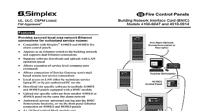
Wimplex Bridge Card Bridge Card allows an FSK modem equipped Series Fire Alarm 4100 0121 2120 0243 Panel or a 2120 CPU to connect up to ten remote FSK modem equipped Fire Alarm Control Panels 4020 Fire Alarm Control Panels and or 4002 Fire Alarm Control Panels Card and voice grade Each remote FSK modem equipped its specific data address and the signals are transformer coupled Card to the master FSK modem decoding FSK modem signals are transmitted outputs which are compatible responds Transponders the Modem Bridge Modem Bridge through 1 shows an example of a Modem Bridge Card interconnection CPU OF TEN TELEPHONE TWO PAIRS TRANSPONDER Bridge Interface Card Interconnection Example 1 Each Communications Converter Comm RS 232C can connect four FSK modems The Modem Bridge Card provides up to ten transmit receive one FSK modem Figure 1 shows an FSK modem connected a remote FSK modem Each remote can be one FSK modem equipped 4100 Series Fire Alarm Control Panel 4020 Alarm Control Panel or 4002 Fire Alarm Control Panel 1993 Simplex Time Recorder Co Gardner MA 01441 specifications other U S A were current as of publmtlon are subject change without notice 574 820 1 93 REQUIREMENTS or battery power not required this card CIRCUIT DESCRIPTION OdB sine wave shifting between 1200 Hz and 2200 Hz is applied TB2 This signal TBl and TB3 at a signal strength greater of remote Hz is passed 3 and 4 of Master Terminal of Terminal a of Terminal Blocks TBl or TB3 and the sine wave shifting between 1200 Hz and split into ten equal signals and sent to all of the remote 26dB When a remote unit answers TB2 at a signal strength greater 26dB transmit applied signal MODEM BRIDGE CARD The Modem Bridge Card can only be used with remote FSK modem units Transponders this card must have CTS Clear To Send and RTS Request To Send signal Transponders with these 4100 Series Fire Alarm Control Panels 4020 Fire Alarm Control Panels 4002 Fire Alarm Control Panels Universal Transponders install the Modem Bridge Card perform following procedure Orientate 617 655 mounting plate so that the press nuts are on the right side of the plate Place 565168 Modem Bridge block at the top of the plate Card on the mounting plate press nuts with TB2 four place Fasten card to the mounting plate using four 426 048 6 Torx 3 8 inch screws Figure 2 Securely four screws No 6 Torx screws 7.9 to 8.7 inch ounces Modem Bridge Interface Card on the Mounting Plate Mount completed assembly the U T cabinet equipment below the FSK Modem mounting plate 2 THE MODEM BRIDGE CARD INSTALLATIONS SAVE ALL RAM BASED PROGRAMS BEFORE REMOVING AC POWER Disconnect batteries supplied and remove AC power before wiring equipment Refer to the following Field Wiring Diagrams and or figures proper connections 565 l 68 Card Interconnections Style 6 and Style 4 Figure 3 Remote 4002 Style 7 Figure 4 and FWD 841 669 Remote 4002 Style 4 Figure 5 and FWD 841 669 Remote 4020 4100 Style 7 Figure 6 and FWD 841 842 Remote 4020 4100 Style 4 Figure 7 and FWD 841 842 or FWD 841 731 or FWD 841 731 SET FOR 1200 UNITS TEL LINES RBOVE L 1 LINES RRE FOR STYLE 6 AS PRIMRRY 68 Card Interconnections Style 6 and Style 4 3 2120 0243 4100 0121 2120 0243 4100 0121 INSTALLED WIRING TO BE MINIMUM 18 AWG OR TO LOCAL CODE 4 4002 Style 7 2120 0243 4100 0121 CR INSTALLED WIRING TO BE MINIMUM 18 AWG OR TO LOCAL CODE 5 4002 Style 4 2120 0243 4100 0121 T INSTALLED WIRING TO BE MINIMUM 18 AWG OR TO LOCAL CODE 6 4020 4100 Style 7 I I 2120 0243 4100 0121 INSTALLED WIRING TO BE MINIMUM 18 AWG OR TO LOCAL CODE 7 4020 4100 Style 4 CHANGES REQUIRED Card will operate with 2120 4100 4020 and 4002 systems when following Modem Bridge are made SYSTEMS 2120 Master Software must be at Revision 5.42 or higher DIP Switch S2 on the CPU card must be changed 1 l previously 300 BAUD on the channel be Upon warm starting system printer should Modem showing modem is 1200 Baud AND 4100 SYSTEMS To Send To Send the installation Add a wire from pin 4 of the 25pin connector on the modem to the RS 232 motherboard FITS Add a wire from pin 5 of the 25pin connector on the modem to the RS 232 motherboard CTS to be Style 7 one line must have a 1 K Ohm l 2 Watt resistor in series with the circuit Change modem DIP switch to the following positions Position 6 Open OFF Position 7 Open OFF Update 565 004 Card software Version 1.06.01 or higher 2120 RS 232 Software P N 740 684 SYSTEMS card must be Revision F or higher Add a wire from pin 4 of the 25 pin connector on the modem to TBl 9 Add a wire from pin 5 of the 25 pin connector on the modem to TBl 10 the installation to be Style 7 one line must have a 1 K Ohm l 2 Watt resistor series with the circuit Change modem DIP switch to the following positions Position 6 Open OFF Position 7 Open OFF that jumper P3 on the interface card is in the J2 position Make certain the software version 1.02.01 or higher THE INSTALLATION Restore AC power to equipment and connect batteries supplied Verify operation of the Modem Bridge Interface Card before returning system to service