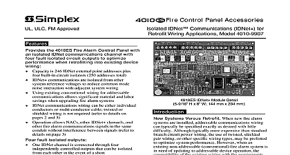
Simplex 4100-3107 Isolated IDNet Communications (IDNet+) for Retrofit Wiring Applications; has four short circuit fault isolated outputs (B)

File Preview
Click below to download for free
Click below to download for free
File Data
| Name | simplex-4100-3107-isolated-idnet-communications-idnet-for-retrofit-wiring-applications-has-four-short-circuit-fault-isolated-outputs-b-3185624709.pdf |
|---|---|
| Type | |
| Size | 903.83 KB |
| Downloads |
Text Preview
ULC CSFM Listed FM Approved NYC Acceptance Control Panels IDNet Communications IDNet for Retrofit Wiring Applications Model 4100 3107 the 4100ES or 4100U Fire Alarm Control with an isolated IDNet communications with four fault isolated circuit outputs to performance when retrofitting into existing wiring Capacity is 246 IDNet external point addresses plus built in circuit isolators 250 addresses total communications are isolated from other reference voltages to reduce common mode interaction with adjacent system wiring Using existing conventional wiring for addressable allows significant material and labor when upgrading fire alarm systems communications wiring can be either individual or multi conductor cable twisted or wiring is not required refer to details on 2 and 3 Operation allows NACs other IDNet channels and fire alarm communications signals in the same without interference between signals refer to on page 3 fault isolated outputs One IDNet channel is connected through four controlled outputs that can be isolated each other in the event of a short Each output is individually on board selectable for Class A or Class B operation intermixed on the IDNet module as desired For Class B wiring multiple connections are available installation convenience each output provides two of parallel connected output terminals with each sized to allow two wires Wiring terminals are rated for up to two 12 AWG per terminal Standby current requirements are the same as existing IDNet expansion modules Outputs are compatible with remote IDNet Isolators Isolator Bases Listed to Standard 864 built in service tools On board trouble LEDs activate per output Ground Fault Detection Diagnostics test each output Duplicate Device Detection and Weak Answer Detection assist in locating devices installed incorrectly in conflict with wiring specifications Device Detect Capability polls all devices determines type of each address and provides Service Port to the results Output troubles with custom labeling are indicated at the panel per output IDNet addressable communications are protected by us Patent No 4,765,025 IDNet device detection is protected under us Patent No 6,034,601 IDNet Module Detail H x 8 W 144 mm x 204 mm Systems Versus Retrofit When new fire alarm are installed addressable communications wiring typically be specified exactly as desired with little Although typically more expensive than standard circuit power wiring the use of twisted shielded wiring or other specific wiring types may be preferred optimize system performance However when an non addressable conventional fire alarm system is need of updating to addressable device operation the of the existing wiring with the requirements the new device communications wiring must be Digital communications wiring audio wiring notification appliance circuit NAC wiring other related power wiring with repetitive switching all have the potential to couple portions of their into each other if their wiring is in close proximity as within the same conduit Sometimes the result is but often the result can be intermittent or interference unless twisted shielded pair TSP twisted pair UTP or shielded wire is used on both or all of the signals involved Operation with Existing Wiring 4100ES Module 4100 3107 uses on board circuitry to the IDNet communications channel from the power conductors to provide an isolated IDNet channel An isolated IDNet channel IDNet significantly improves common mode rejection and allows a variety of fire alarm signals to non interfering when wired in the same conduit this module provides four fault isolated capable of being selected as Class A or Class B intermixed on the same module This product has been approved by the California State Fire Marshal CSFM pursuant to 13144.1 of the California Health and Safety Code See CSFM Listing 7165 0026 251 allowable values and or conditions concerning material presented in this document It is to re examination revision and possible cancellation Additional listings may be contact your local Simplex product supplier for the latest status Listings and under Simplex Time Recorder Co are the property of Tyco Safety Products Specifications System Specifications and Input Output Specifications System Software Revision or 4100U Revision 11.10 or higher Device Compatibility reference data sheet S4090 0011 for details Voltage VDC system supplied Current only 75 mA Alarm 115 mA add IDNet device loading see below Alarm 361 mA with 246 remote devices Devices Per device Supervisory 0.8 mA Alarm 1 mA 30 VDC nominal 36 VDC maximum DC voltage with imposed data Output 500 mA maximum Up to 246 remote devices outputs are assigned addresses 247 to 250 Wiring Specifications Maximum wiring distance is determined by either reaching the maximum capacitance the total series wiring or the stated maximum distance whichever occurs first Parameters for Class A or Class B wiring Individual IDNet Channel Capacitance sum of line to line capacitance the capacitance of either line to shield if is present 0.6 maximum total of all four outputs Channel to Channel Wiring for multiple IDNet SLCs between any one IDNet Channel and other IDNet Channels 1 measured between wires of the same polarity plus to plus Channel Wiring Resistance A Wiring Resistance B Wiring Resistance to 125 devices 50 to 246 devices 35 maximum Total series wire resistance of all four maximum loops to 125 devices 50 to 246 devices 35 maximum Total series wire resistance of all four maximum including any Wiring Distances distance may be less due to capacitance and resistance specifications Channel Maximum Wiring ft 3.8 km total for all four outputs Class A or Class B including Class B wiring Distance Limits A wiring loop distance limit per B wiring maximum distance the panel to the farthest device on output Wiring Considerations using Overvoltage Protectors listed to Standard 1459 Standard Telephone Equipment to data sheet S2081 0016 for details Size to 125 devices to 246 devices AWG ft 1219 m ft 762 m to 12 AWG ft 1524 m ft 762 m 18 AWG 0.82 mm2 16 AWG 1.31 mm2 14 AWG 2.08 mm2 12 AWG 3.31 mm2 Wiring that leaves the building must be shielded for lightning suppression 2081 9044 Overvoltage Protectors must be installed at building exit and locations each protector adds 0.006 across the connected line each protector adds 3 protected 6 per protector will be added to total loop resistance per line of series resistance both IDNet lines maximum distance of a single protected wiring run is 3270 ft 1 km Mechanical and Environmental Specifications LED Display Capacity to 20 maximum remote device LEDs can be activated simultaneously Sounder Base Capacity to 43 sounder bases may be coded by IDNet communications when the is powered by 24 VDC not applicable to NAC powered sounder bases Requirements page 4 for additional reference x 8 144 mm x 203 mm module requires two consecutive horizontal two maximum are allowed per expansion bay mounting is left and right Temperature Range F to 120 F 0 C to 49 C Range to 93 RH non condensing 94 F 38 C Equipment Considerations Equipment Considerations Cont Equipment When performing a retrofit with the 4100 3107 IDNet Module review the important considerations All existing devices whether conventional or must be located and removed Only IDNet compatible devices are allowed on IDNet channel Refer to data sheet S4090 0011 for Addre