Simplex 4100 4120-Series Physical Bridges & Media Modules - Installation Instructions

File Preview
Click below to download for free
Click below to download for free
File Data
| Name | simplex-4100-4120-series-physical-bridges-media-modules-installation-instructions-4362978105.pdf |
|---|---|
| Type | |
| Size | 2.49 MB |
| Downloads |
Text Preview
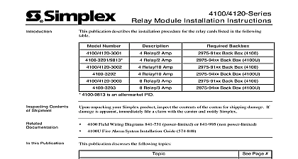
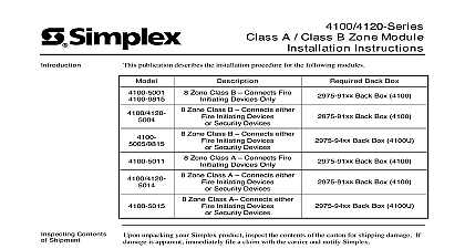
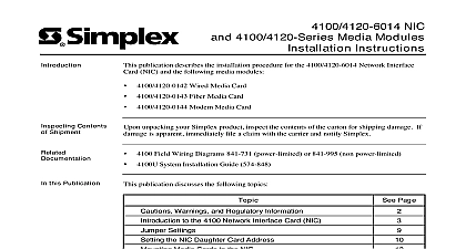
F I R E Bridges Media Modules and Trademarks Simplex Time Recorder Co 2001 All rights reserved in the United States of America in this document is subject to change without notice No part of this document may reproduced or transmitted in any form or by any means electronic or mechanical for any without the express written consent of Simplex Time Recorder Company and the Simplex logo are registered trademarks of Simplex Time Recorder Co and Warnings AND SAVE THESE INSTRUCTIONS Follow the instructions in this installation These instructions must be followed to avoid damage to this product and associated Product operation and reliability depends upon proper installation NOT INSTALL ANY SIMPLEX PRODUCT THAT APPEARS DAMAGED Upon your Simplex product inspect the contents of the carton for shipping damage If is apparent immediately file a claim with the carrier and notify Simplex HAZARD Disconnect electrical field power when making any internal or repairs Servicing should be performed by qualified Simplex Representatives HAZARD Static electricity can damage components Therefore handle as follows Ground yourself before opening or installing components use the 553 484 Static Control Prior to installation keep components wrapped in anti static material at all times SAFETY HAZARD Under certain fiber optic application conditions the optical output of device may exceed eye safety limits Do not use magnification such as a microscope or other equipment when viewing the output of this device FREQUENCY ENERGY This equipment generates uses and can radiate radio energy and if not installed and used in accordance with the instruction manual may interference to radio communications It has been tested and found to comply with the for a Class A computing device pursuant to Subpart J of Part 15 of FCC Rules which are to provide reasonable protection against such interference when operated in a environment Operation of this equipment in a residential area may cause interference which case the user at his own expense will be required to take whatever measures may be to correct the interference REACCEPTANCE TEST AFTER SOFTWARE CHANGES To ensure proper operation this product must be tested in accordance with NFPA72 1996 Chapter 7 after programming operation or change in site specific software Reacceptance testing is required any change addition or deletion of system components or after any modification repair or to system hardware or wiring components circuits system operations or software functions known to be affected by a must be 100 tested In addition to ensure that other operations are not inadvertently at least 10 of initiating devices that are not directly affected by the change up to a of 50 devices must also be tested and proper system operation verified Bridges Media Cards Style 4 Physical Bridge for 2975 91xx Back Boxes 4100 Style 7 Physical Bridge for 2975 91xx Back Boxes 4100 Style 4 Physical Bridge for 2975 94xx Back Boxes 4100U Style 4 Physical Bridge for 2975 94xx Back Boxes 4100U publication describes the installation procedure for the following Style 7 Interface for 2975 91xx Back Boxes 4100 Modem Media Card Wired Media Card Fiber Media Card Contents Shipment unpacking your Simplex product inspect the contents of the carton for shipping damage If is apparent immediately file a claim with the carrier and notify Simplex Field Wiring Diagrams 841 731 power limited or 841 995 non power limited Fire Alarm System Installation Guide 574 848 this Publication publication discusses the following topics Page with Physical Bridges to the Physical Bridge Card Numbers Switch and Jumper Settings Motherboards into 2975 91xx Back Boxes 4100 Motherboards into 2975 94xx Back Boxes 4100U Media Cards the Network Modem Daughter Cards Guidelines Procedure Networking with Physical Bridges bridges are cable connections between 4100 series network nodes They are the means by each node in a system communicates with the other and with the master controller most cases the cable that makes up the physical bridge connects to two physical bridge cards card per network node The physical bridge card is basically a 4100 network interface card three communication ports the usual left and right network ports plus a bridging port The port combined with the modem media module communicates with the remote network bridge card over dedicated leased telephone lines using a special Simplex developed protocol that enables full duplex communication between physical bridge cards a typical configuration one physical bridge card represents all the nodes in the main loop and information over the bridge to the remote physical bridge card and network In order for the physical bridge card to accept information intended for another node in its remote loop the bridge card becomes a proxy it assumes the identity of that specified node The is finally sent from the remote physical bridge card to the specified node on next page with Physical Bridges Continued Systems systems support two prevalent architectures or wiring configurations hub or ring star A networked system can also use a combination of the two and Star hub configuration consists of a main loop with nodes connected in a radial manner The star consists of several nodes connected directly to one common node Physical bridge are used for the star configuration Physical bridges reduce the amount of wire that would be needed to connect all nodes in a loop and therefore cut down on system response A combination of the two styles is illustrated in Figure 1 Topology Command GCC Display Unit Hub Node Bridge Links Topology Remote Locations 1 Hub Ring Configuration on next page with Physical Bridges Continued Loops loops can be joined via physical bridge cards There may be no more than two Style 7 loops two hub configurations connected in tandem For every two loops that are using one physical bridge there can be a maximum of three physical bridges in a star configuration See Figure 2 e m o t e o d e Loop u b o d e Loop Node Bridge Link Command GCC Bridge Link Bridge Link Bridging Configuration 2 Interconnected Loop Configuration to the Physical Bridge Card physical bridge card is used to connect up to 98 remote 4100 network nodes using leased lines 3 depicts the network physical bridge card and its motherboard TRANSMIT LEDs THROUGH CARD P6 RATE JUMPER P3 PORT SWITCH SW2 LED SWITCH MEDIA TB1 CARD J2 P4 MEDIA TERMINAL BRIDGE CARD Card BRIDGE 3 4100 Network Physical Bridge Assembly on next page to the Physical Bridge Card Continued Bridge Indications Module TYPE PORT NETWORK CARD J1 PORT physical bridge card has the following LEDs yellow Off when the physical bridge card is operating normally