Simplex 4100-6036, 4100-6037, 4010-9903, 4010-9904 Network Interconnections, Physical Bridge Modules (A) (B)

File Preview
Click below to download for free
Click below to download for free
File Data
| Name | simplex-4100-6036-4100-6037-4010-9903-4010-9904-network-interconnections-physical-bridge-modules-a-b-7509812364.pdf |
|---|---|
| Type | |
| Size | 844.17 KB |
| Downloads |
Text Preview
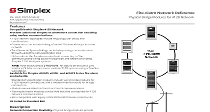
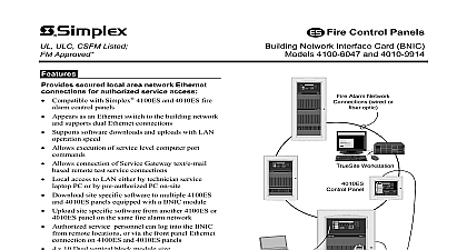
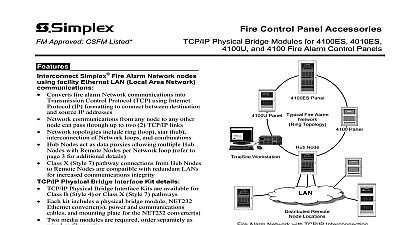
ULC CSFM Listed FM Approved NYC Acceptance additional Simplex Fire Alarm Network flexibility using modem Network topologies include ring loop star hub combinations one network Connections can include linking of two Network loops Total Network System linking can include passing through up to three 3 physical links Hub nodes in the fire alarm control panel connecting Star communications wiring assist in expansion and of existing Simplex 2120 Multiplex systems for Simplex 4100ES 4100U and Series fire alarm control panels Standard Physical Bridge modules include wired modules for Network connections and a modem module for bridge connections Models are available for Class B or Class X Fiber optic media modules can be field installed as for Network communications Also compatible with legacy 4100 4100 4020 Series panels Listed to Standard 864 Connection Flexibility Physical bridge provide an intelligent network link that increases flexibility of Simplex fire alarm Networks between the physical bridge modules a proprietary full duplex two wire modem protocol efficient information transfer Additionally each bridge module functions as a for its node information to maintain overall network Network Loop Connections Connection include linking of two network loops into one branching to single or multiple remote nodes existing two wire connections creating hub nodes form Star configuration systems and combinations of connections providing convenient networking Alarm Network Reference Network Interconnections Bridge Modules SY ST EM I S NO RM AL 2 02 1 5p m Mon 8 M ar 9 9 R YST EM ROUBL RM LENCED WER K K LA RM CE EM ESE IR E AL AR M T RO L SCO NN EC T ER BE FO RE VICING Fire Alarm Control Control Bridge Module Link Connected Node a Single Remote Node This product has been approved by the California State Fire Marshal CSFM pursuant to 13144.1 of the California Health and Safety Code See CSFM Listing for allowable values and or conditions concerning material presented in document It is subject to re examination revision and possible cancellation for use City of New York Department of Buildings MEA35 93E Additional may be applicable contact your local Simplex product supplier for the latest Listings and approvals under Simplex Time Recorder Co are the property of Fire Protection Products Refer to data sheet S4190 0016 for details on the Serial Line Interface SLI for to multiple 2120 systems using a TrueSite workstation 9 2012 Product Selection for 4100ES and 4100U 4 Module Physical Bridge Class B Physical Bridge Class X Fiber optic media module Order separately as needed to replace wired Details one modem module and 2 wired modules two modem modules and 2 wired modules modules on site per system requirements 8 VDC Converter Module Required for multiple Physical Bridge Modules 7 Module A maximum Space Requirements slot size slot size to Modular Network Interface block module 4 x 5 card for or 4100U only not applicable 4010ES for 4010ES Physical Bridge Class B 4 Module Details one modem module and 2 wired modules Physical Bridge Class X 7 Module two modem modules and 2 wired modules Space Requirements vertical blocks vertical blocks Fiber optic media module Order separately as needed to replace wired modules on site per system requirements to Modular Network Interface Refer to data sheet S4010 0004 for additional mounting details For international applications refer to data sheet S4010 0006 Hub Node Connection to Star Topology to Star Connections The diagram to the illustrates the use of multiple physical bridge to allow a conventional ring topology to interface into a Star topology Each bridge link requires a physical bridge at each end A network interface module required at each node to complete the network path refer to internal block on pages 3 and 4 for additional Capability This example illustrates flexibility available when retrofitting existing connection topology system wiring such as replacement of Simplex 2120 series Multiplex alarm control panels Control Alarm Network Topology SYSTE M IS N OR MA L 2 0 2 15p m M on 8 M ar 99 ROUBL STEM ARM LARM OUBLEACK ARM ENCE IR E AL AR M ON T RO L ISCONN EC T WER BE FO RE VICING Workstation Display Unit Hub Node Bridge Links Topology Control Control Remote Locations 9 2012 Additional Applications diagram below illustrates Network connection using Physical Bridges Network nodes can through up to three 3 physical bridge as indicated by the arrows Star topology each link once back to the hub node and then using standard Network wired connections the shaded section below with three 3 Physical links up to four 4 separate Network loops can be without Star connections Node Bridge Link Control Control Loop Control Control Loop Workstation Node Bridge Link Workstation Bridge Links Control Bridging Configuration Control 1 2 3 4 to Four Network Loops can be using 3 Physical Bridges Basic Physical Bridge Block Diagram preceding node A Interface or per line if one B Interface Loop next node Bridge Connection B or Class X Class B Bridge Bridge Wired media card Modem media card Wired or fiber optic media per application requirement next or per line only one 9 2012 Specifications for additional information refer to Installation Instructions 579 184 Haul Twisted Pair Lines Distance Haul Leased Telco Lines Distance and Data Information B Style 4 Connection X Style 7 Connection Rate Requirements and Environmental or 4010 9924 Class B or 4010 9925 Class X 4100 6057 Fiber Optic Media Temperature Humidity AWG 9500 ft 2.85 km AWG 15,000 ft 4.5 km Unlimited leased lines for analog data point to point full duplex no line conditioning or required two wire line interface 2 wire RJ 11 Interface 2 wire RJ 11 Interfaces to 14.4 kbps to 38.4 kbps using MNP 5 compression and error correction Alarm 210 mA 24 VDC system power Alarm 300 mA 24 VDC system power media module in use reduces above currents by 30 mA to 120 0 to 49 C to 93 RH non condensing 90 F 32 C maximum Physical Bridge Hub Node to Multiple Star Connections Block Diagram Loop Interface Module Bridge Module 1 Class B Bridge Module 2 Class B Bridge Module 3 Class X Wired media card Modem media card Wired or fiber optic