Simplex 4100-6046 Dual RS-232 Interface Module

File Preview
Click below to download for free
Click below to download for free
File Data
| Name | simplex-4100-6046-dual-rs-232-interface-module-0972631548.pdf |
|---|---|
| Type | |
| Size | 997.51 KB |
| Downloads |
Text Preview
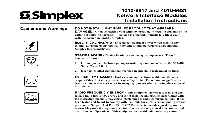
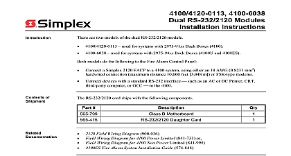
Installation Instructions RS 232 Interface Module 4100 6046 4100U 4100ES AND SAVE THESE INSTRUCTIONS Follow the instructions in this installation manual These instructions must be to avoid damage to this product and associated equipment Product operation and reliability depend upon proper NOT INSTALL ANY SIMPLEX PRODUCT THAT APPEARS DAMAGED Upon unpacking your Simplex product the contents of the carton for shipping damage If damage is apparent immediately file a claim with the carrier and notify authorized Simplex product supplier HAZARD Disconnect electrical field power when making any internal adjustments or repairs All repairs should performed by a representative or authorized agent of your local Simplex product supplier HAZARD Static electricity can damage components Handle as follows Ground yourself before opening or installing components Prior to installation keep components wrapped in anti static material at all times RULES AND REGULATIONS PART 15 This equipment has been tested and found to comply with the limits for a Class A digital pursuant to Part 15 of the FCC Rules These limits are designed to provide reasonable protection against harmful interference when the is operated in a commercial environment This equipment generates uses and can radiate radio frequency energy and if not installed used in accordance with the instruction manual may cause harmful interference to radio communications Operation of this equipment in a res area is likely to cause harmful interference in which case the user will be required to correct the interference at his own expense REACCEPTANCE TEST AFTER SOFTWARE CHANGES To ensure proper system operation this product must be tested in with NFPA 72 after any programming operation or change in site specific software Reacceptance testing is required after any change or deletion of system components or after any modification repair or adjustment to system hardware or wiring components circuits system operations or software functions known to be affected by a change must be 100 tested In addition to ensure that operations are not inadvertently affected at least 10 of initiating devices that are not directly affected by the change up to a maximum of 50 must also be tested and proper system operation verified dual RS 232 interface module 4100 6046 is a Fire Alarm Control Panel FACP 4x5 interface that communicates to an an AC or a DC printer a CRT a third party computer or to a GCC to the It is used for systems with 2975 94xx back boxes Supervised or unsupervised devices can be to either port to both ports can be either isolated or non isolated The isolated power is intended for AC printers or Ground faults can result if isolated power is not used for AC devices GCCs and third party DC printers use the non isolated power SimplexGrinnell LP All rights reserved and other information shown were current as of publication and are subject to change without notice and the Simplex logo are trademarks of Tyco International Ltd and its affiliates and are used under license B of unpacking your Simplex product inspect the contents of the carton for shipping damage If is apparent immediately file a claim with the carrier and notify your local Simplex supplier The dual RS 232 interface module is shipped with the 566 798 dual RS 232 module component 4100 Field Wiring Diagrams 841 731 power limited or 841 995 non power limited 4100ES Fire Alarm System Installation Guide 574 848 this publication discusses the following topics Page Jumpers Switches the 4100 6046 Dual RS 232 Flat Card 4X5 Module into 2975 94xx Back Boxes following terms are defined Ray Tube standard TV computer desktop monitor Package Alarm Control Panel Command Center Distribution Interface 24VDC normal operation 60 mA Maximum fault conditions 90 mA Operating temperature 32oF to 120oF 0oC to 49oC Humidity up to 93 relative humidity at 90oF 32oC Jumpers 1 shows the locations of the jumpers on the dual RS 232 interface module and identifies number assigned to each jumper pin The specific jumper settings required on the dual RS 232 module depend on the type of device being attached to the card Refer to Table 1 for jumper configurations 1 Location of Jumpers Jumpers Continued Settings Specific 1 lists the jumper settings for the range of devices that can be attached to the dual RS 232 module to Figure 1 for the locations of the jumpers and their corresponding pin numbers In Table 1 means you should place the jumper on pins 2 and 3 whereas a designation of 1 2 means you place the jumper on pins 1 and 2 1 Jumper Settings for Dual RS 232 Interface Module B A AND P4 AND P6 PRINTER PRINTER PRINTER PRINTER Switches SW1 on the dual RS 232 interface module is a bank of eight DIP switches From left to see Figure 2 these switches are designated as SW1 1 through SW1 8 The function of these is as follows SW1 1 This switch sets the baud rate for the internal FACP communications line running the card and the FACP CPU Set this switch to ON SW1 2 through SW1 8 These switches set the card address within the FACP Refer to 2 for a complete list of the switch settings for all of the possible card addresses must set these switches to the value assigned to the card by the FACP Programmer Rate SW 1 1 Be Set to Switches 1 2 through 1 8 the card address Figure 2 an address of 3 Refer Table 2 for a list of settings 2 Address DIP Switch the 4100 6046 Dual RS 232 Flat Card 1 2 1 3 1 4 1 5 1 6 1 7 1 8 1 2 1 3 1 4 1 5 1 6 1 7 1 8 2 FACP Daughter Card Addresses