Simplex 4100-9342, -9542 4100ES Network Annunciator Panels; Network Display Units with Voice Command Center and EPS+ Power Supplies; with IDNAC notification (A) (B) (G)

File Preview
Click below to download for free
Click below to download for free
File Data
Text Preview
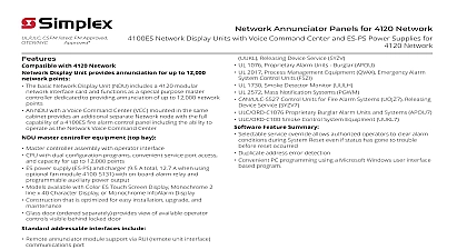
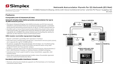
ULC CSFM Listed Approved Network Annunciator Panels Network Display Units with Voice Center and EPS Power Supplies Display Unit NDU provides for up to 12,000 network points The basic NDU is a special purpose master controller includes a network interface module An NDU with a Voice Command Center VCC in the same cabinet provides an additional Network node within the same cabinet for of Network level Emergency Voice Alarm Equipment master controller equipment top bay Master controller assembly with operator interface 4100ES CPU with dual configuration programs service port access and capacity for up to points System power supply SPS and charger 9 A total on board programmable auxiliary output Operator interface that is conveniently color coded raised switches providing high confidence Available with InfoAlarm Command Center expanded user interface refer to data sheet S4100 0101 addressable interfaces include Remote annunciator module support via RUI remote interface communications port field installed option modules include DACT and City Connection Service modems for remote panel status inquiry RS 232 ports for printers or maintenance terminals Alarm relays and expansion power supplies SafeLINC Internet Interface equipment second expansion bay VCC include Enhanced Power Supply EPS and charger 9 A total with on board IDNAC signaling line circuit for addressable appliance IDNet 1 isolated addressable device control and programmable function auxiliary output For additional information concerning EPS power and their enhanced features refer to 4100ES sheet S4100 0100 and refer to additional related data sheet list on page 9 Voice control options are similar to a networked fire control panel with an extensive list of modules for initiating notification and user interface This product has been approved by the California State Fire Marshal CSFM pursuant to 13144.1 of the California Health and Safety Code See CSFM Listing for allowable values and or conditions concerning material presented in document Additional listings may be applicable contact your local Simplex product for the latest status Listings and approvals under Simplex Time Recorder Co are property of Tyco Fire Protection Products 4 4100U DOWN Control DOWN DOWN 3 4100ES 5 4100ES NDU with VCC 1 and Node 2 B C K L T U E F N O W X 0 H I Q R Z Alarm Priority 2 Alarm STEM WARNINGS Silenced C P ower Alarm riority 2 isarm or Warning Co ndition indicator f lashing Tone On to A cknowledge View Events ACK located under f lashing indicator operat ion unt il all events are acknowledged tone will silence to Silence Building Sig nals Alarm Silence to Re set System System Reset Ack to silence tone device Operating Instructions f uto f uto f uto f uto f f f f One Line Diagram Showing an NDU with VCC to UL Std 864 Fire Detection and Control UOJZ and Control Service UUKL UL Std 2017 Process Management Equipment QVAX UL Std 1076 Proprietary Alarm Units Burglar APOU UL Std 1730 Smoke Detector Monitor UULH ULC Std S527 Control Units for Fire Alarm Systems 4100ES NDU with VCC is a network level and manual system point controller with voice control equipment It provides annunciation for up to 12,000 Network and or point lists and can be programmed to as the network master controller for Alarm Trouble Acknowledge and System Reset 5 2013 Introduction Continued Network Overview When connected to other Network individual fire alarm control panels become of a distributed intelligence system Each that directly connects to the network is called a and is capable of performing individual and control on its locally connected devices has the ability to inform the 4100ES NDU as well as network control panels of point status and panel This allows system information to reach the location for appropriate system response 4100ES NDUs separately packaged can be to a Network to duplicate common information separate locations or direct selected information by such as troubles alarms control etc Module Bay Description The NDU Master Controller Bay top includes a purpose system power supply with battery charger the master controller board a Network Interface and operator interface equipment similar to that on the standard fire alarm control modules Slots 1 2 are available for single slot panel mounted modules VCC includes an expansion bay with separate controller board Network Interface Module and EPS power supply This results in two separate nodes residing within the same cabinet the VCC bay a dual PDI connection is available for a dual slot module or one or two block modules LED switch modules can also be mounted For cabinets the VCC mounts in bay 2 For 3 bay as shown to the right the VCC mounts in the expansion bay bay 3 Battery Compartment bottom accepts two up to 50 Ah to be mounted within the cabinet interfering with module space to the NDU with VCC internal module bay illustration for typical three bay cabinet module Interface Detail Reference following illustration identifies the primary functions the operator interface interface panel is directly and accessible no access door B C K L T U E F N O W X 0 H I Q R Z WARNINGS Alarm 2 Alarm Silenced Power Alarm 2 or Warning Condition indicator flashing Tone On to Acknowledge View Events ACK located under flashing indicator operation until all events are acknowledged tone will silence to Silence Building Signals Alarm Silence to Reset System System Reset Ack to silence tone device Operating Instructions Master Bay 1 2 Controller Board 3 is Network Interface 4 is Master Controller 1 2 3 4 5 6 7 8 1 2 3 3 4 Power Pwr Bay 1 1 2 3 4 5 6 7 8 Wiring Wiring power supply Module E Module F Wiring Power G H bay with module sizes Controller Board 3 is Network Interface 4 is Master Controller 1 2 3 4 with VCC Bay 2 board with two available Compartment Power Supply IDNet 1 Module with VCC Internal Module Bay Reference exact is determined by specific system requirements Packaging Availability Modules are power limited unless specifically noted Enclosure are available for one two or three bay sizes for cabinet rack mounting Additional cabinets can be mounted close nippled for expansion Boxes doors with tempered glass inserts and dress are available in beige or red ordered Refer to data sheet S4100 0037 for enclosure details Feature Summary Selectable service overr