Simplex 4100 Series InfoAlarm Command Center for the 4100ES Fire Alarm Control Panel; panel mounted and remote cabinet mounted (B)

File Preview
Click below to download for free
Click below to download for free
File Data
| Name | simplex-4100-series-infoalarm-command-center-for-the-4100es-fire-alarm-control-panel-panel-mounted-and-remote-cabinet-mounted-b-1962705834.pdf |
|---|---|
| Type | |
| Size | 1.23 MB |
| Downloads |
Text Preview
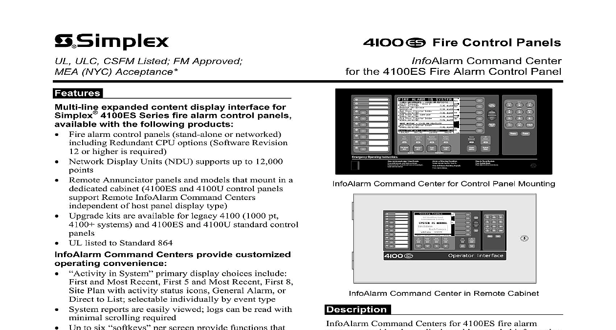
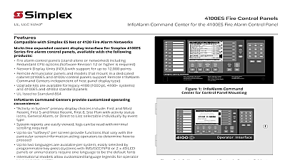
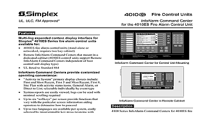
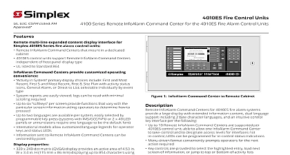
ULC CSFM Listed FM Approved NYC Acceptance Control Panels InfoAlarm Command Center the 4100ES Fire Alarm Control Panel expanded content display interface for 4100ES Series fire alarm control panels with the following products Fire alarm control panels stand alone or networked Redundant CPU options Software Revision or higher is required Network Display Units NDU supports up to 12,000 Remote Annunciator panels and models that mount in a cabinet 4100ES and 4100U control panels Remote InfoAlarm Command Centers of host panel display type Upgrade kits are available for legacy 4100 1000 pt systems and 4100ES and 4100U standard control UL listed to Standard 864 Command Centers provide customized convenience in System primary display choices include and Most Recent First 5 and Most Recent First 8 Plan with activity status icons General Alarm or to List selectable individually by event type System reports are easily viewed logs can be read with scrolling required Up to six per screen provide functions that with the particular screen information aiding to determine how to proceed Up to two languages are available per system easily by programmable key press systems with or 2 x 40 LCD panels or annunciators one language to be the default font models allow customized language legends operator keys and status LEDs properties 320 x 240 dot matrix QVGA display provides an active of 4.53 W x 3.4 H 115 mm x 86 mm displaying to 854 characters using standard ASCII character font Bright white LED backlighting provides efficient and lasting illumination operation is selectable as or off with power fail or with no key presses Displaying more information 4100ES Controls using the Command Center provide an expanded content LCD interface that requires minimal key presses to detailed information Because it is system powered its information is provided without requiring separate equipment Command Center Control Panel By using larger area format instead of an individual text line display LCD provides text information for Alarm Supervisory or The format is flexible and able to be customized per allowing additional information to be presented to the specific application Up Dn B C K L T U E F N O W X H I Q R Z 2 Alarm 2 Operating Instructions to Acknowledge View Events ACK located under flashing indicator operation until all events are acknowledged tone will silence or Warning Condition indicator flashing Tone On to Silence Building Signals Alarm Silence to Reset System System Reset Ack to silence tone device Command Center for Control Panel Mounting Up Dn B C K L T U E F N O W X H I Q R Z 2 Alarm 2 Command Center in Remote Cabinet Command Centers for 4100ES fire alarm provide a large display with extended information dual language support including 2 byte character and an intuitive control key interface per the Up to 10 InfoAlarm Command Centers are supported per control panel able to allow one Command Center to take control and to access levels for interfaces not in control LEDs be programmed for in control status indications Menu driven format conveniently prompts operators for next action required Key controls are provided to select the highlighted entry next screen of information or jump to top or of activity lists Direct point callup displays individual points and then homes in on the logical choice as point information is entered A Site Plan bitmap can be displayed for reference icons be added to indicate system status Up to 50 custom point detail messages can be generated Date formats are either MM DD YY or DD MM YY Time formats are either 24 hour or 12 hour with AM PM System Normal screen supports a gray scale bitmap for location name company logo or site plan This product has been approved by the California State Fire Marshal CSFM pursuant to 13144.1 of the California Health and Safety Code See CSFM Listing 7165 0026 251 allowable values and or conditions concerning material presented in this document It is to re examination revision and possible cancellation Accepted for use City of York Department of Buildings MEA35 93E Additional listings may be applicable your local Simplex product supplier for the latest status Listings and approvals under Time Recorder Co are the property of Tyco Fire Protection Products 3 2012 Control Panel Operation Reference Refer to page 7 for international control panel reference information Detailed operator instructions are on 579 685 x 240 DOT MATRIX DISPLAY White backlighting provides easy viewing is programmable for key inactivity and or AC power fail ACTIVITY IN SYSTEM OPTIONS Choices include First shown below for Fire Alarm in System and Most Recent First 5 and Most Site Plan General Alarm or to List After the event is screen reverts to the event list until Clr Exit softkey is or after timeout 30 seconds to Fire Alarm Priority 2 Alarm Supervisory and System Trouble category is independently selectable primary display mode SOFT KEYS are available when This sample provides Menu call up the available operations Info to call up specific point Site to call up the Site Plan Screen Event Time while displays time and date for all events and Clr Exit the are other typical soft keys Enable and Disable On or Arm Off or Disarm On Off or to Auto Mode Time Request Information Request PROGRAMMABLE provide custom labeling top two LEDs are selectable red or yellow the third LED is as red or green SYSTEMS require a Ground Fault label insert typical shown for reference KEYPAD for category and point alphabet are not used this time Key duplicates Clr Exit softkey present Fault Evac Disconnect Holder Sensor Dirty Check Test PROGRAMMABLE SWITCHES each with dual color LED the top six LEDs are as either red or the bottom LED is as either red or NOTE Program the switch as Lamp for UL listed systems Up Dn B C K L T U E F N O W X H I Q R Z NAVIGATION Enter Previous select Next item Page Up and Down SYSTEM STATUS INDICATOR provide system status indications addition to LCD information LEDs flash indicate the condition and then when remain on until reset Alarm Priority 2 Alarm red LED Trouble yellow LED Silenced yellow LED Power green LED on for normal 2 Alarm 2 ALARM ACK acknowledges a Fire Alarm condition logs the silences the operator panel and all annuncia


