Simplex 4100U Back Box and Accessories - Installation Instructions

File Preview
Click below to download for free
Click below to download for free
File Data
| Name | simplex-4100u-back-box-and-accessories-installation-instructions-6534978021.pdf |
|---|---|
| Type | |
| Size | 801.99 KB |
| Downloads |
Text Preview
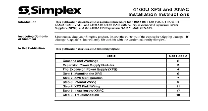
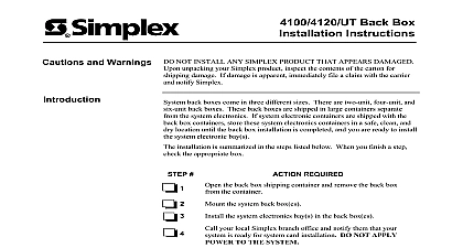
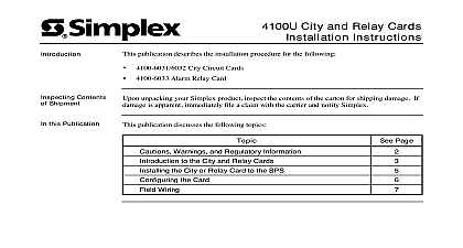
4100U Back Boxes and Accessories Instructions to 9409 Red Back Boxes to 9412 Beige Back Boxes publication describes the installation procedure for the following and 2975 9812 Semi Flush Trim Bands to 2123 Enclosure Doors to 2133 Enclosure Doors Shock Mount Kit Contents Shipment this Publication unpacking your Simplex product inspect the contents of the carton for shipping damage If is apparent immediately file a claim with the carrier and notify Simplex Page publication discusses the following topics and Warnings Back Boxes and Enclosures Back Boxes Card Assemblies to Back Boxes Doors the Shock Mount Kit 2001 Simplex Time Recorder Co Westminster MA 01441 0001 USA specifications and other information shown were current as of publication and are subject to change without notice A and Warnings AND SAVE THESE INSTRUCTIONS Follow the instructions in this installation These instructions must be followed to avoid damage to this product and associated Product operation and reliability depends upon proper installation NOT INSTALL ANY SIMPLEX PRODUCT THAT APPEARS DAMAGED Upon your Simplex product inspect the contents of the carton for shipping damage If is apparent immediately file a claim with the carrier and notify Simplex HAZARD Disconnect electrical field power when making any internal or repairs Servicing should be performed by qualified Simplex Representatives HAZARD Static electricity can damage components Therefore handle as follows Ground yourself before opening or installing components use the 553 484 Static Control Prior to installation keep components wrapped in anti static material at all times SAFETY HAZARD Under certain fiber optic application conditions the optical output of device may exceed eye safety limits Do not use magnification such as a microscope or other equipment when viewing the output of this device FREQUENCY ENERGY This equipment generates uses and can radiate radio energy and if not installed and used in accordance with the instruction manual may interference to radio communications It has been tested and found to comply with the for a Class A computing device pursuant to Subpart J of Part 15 of FCC Rules which are to provide reasonable protection against such interference when operated in a environment Operation of this equipment in a residential area may cause interference which case the user at his own expense will be required to take whatever measures may be to correct the interference REACCEPTANCE TEST AFTER SOFTWARE CHANGES To ensure proper operation this product must be tested in accordance with NFPA72 1996 Chapter 7 after programming operation or change in site specific software Reacceptance testing is required any change addition or deletion of system components or after any modification repair or to system hardware or wiring components circuits system operations or software functions known to be affected by a must be 100 tested In addition to ensure that other operations are not inadvertently at least 10 of initiating devices that are not directly affected by the change up to a of 50 devices must also be tested and proper system operation verified Back Boxes and Enclosures different sizes of system back boxes are available accommodating one two or three bays Back boxes are available either in red or beige and can include either solid or doors of Back Boxes 1 lists the specifications for the various back boxes 1 Back Box Specifications of Doors 2 lists the specifications for the various enclosure doors that each PID listed below is available in red or beige Door colors depend on six digit part 2 Enclosure Door Specifications Type Bay Bays Bays Bay Bays Bays Bay Bays Bays Bay Bays Bays Back Boxes the Back section contains guidelines for flush and surface back box mounting Back boxes are shipped in large containers separate from the system If system electronics containers are shipped with the back box store the system electronics containers in a safe clean and dry until the back box installation is completed and you are ready to install system electronic bay s the back box as shown in Figure 1 Use the holes in the back box to secure it to the wall For mounting to a wooden wall structure the back box must be attached with four lag bolts and four washers For surface mounting secure the box to the wall using the tear drop and mounting on the back surface For flush and semi flush mounting secure the box to the studs using the knockouts on the sides of the box Note that the front surface of box must protrude at least 3 inches from the wall surface for semi flush Power limited systems have back box entrance and routing restrictions for field Do not locate power limited wiring in the areas of the back box shown shaded Figure 1 Do not use the upper right right or bottom knockouts for entrance of wiring Those areas are reserved for non power limited circuitry such AC power batteries and the city connection 29 32 USE 4 HOLES TO BACKBOX TO THE WALL USE 4 HOLES TO BACKBOX TO THE WALL RESERVED FOR BATTERIES NOTE 6 ADDITIONAL BACK BOX 13 32 17 32 17 32 Note 3 Dimensions shown are typical for all surface and semi flush installations Use suitable punch when conduit is required and no knockout is present Minimum distance between boxes is 3 inches Maximum distance between boxes is 6 inches Do not install any power limited wiring in the shaded area of the back box as shown in Figure 1 This area reserved for non power limited devices and circuits for example AC power batteries and city circuits non power limited area is determined by the internal barriers but is always below and to the right of barriers 1 Back Box Installation Diagram Card Assemblies to Back Boxes the Electronics the back boxes have been mounted electronics assemblies are ready to be mounted to the boxes This section describes that process which applies to any kind of electronics assembly into any size cabinet system electronics bays for each back box are secured inside a cardboard shipping container shipped from the factory the following procedure to install the system electronics bays Disconnect the 734 008 Harness from P1 on the power distribution interface PDI Remove everything from the electronics shipping container and set the screws aside Remove the shipping studs that secure the bays to the shipping container DIE CUT HEX NUT REQUIRED LOCK WASHER REQUIRED FLAT WASHER REQUIRED REQUIRED FOAM BLOCK REQUIRED 2 Removing the Shipping Studs on next page Card Assemblies to Back Boxes Continued the Electronics continued Place the power distribution module PDM mounting bracket to the right side of the back box that it hangs on the back box two mounting studs as shown in Figure 3 11 PDM HERE STUDS 3 Mounting the PDM Bracket 2 Bay Box Shown Secure the PDM mounting bracket the two mounting studs with two 6 nuts Securely all mounting screws Refer to Table 3