Simplex 4100U Master Operator Interface - Replacement Instructions
File Preview
Click below to download for free
Click below to download for free
File Data
| Name | simplex-4100u-master-operator-interface-replacement-instructions-2360941875.pdf |
|---|---|
| Type | |
| Size | 954.89 KB |
| Downloads |
Text Preview
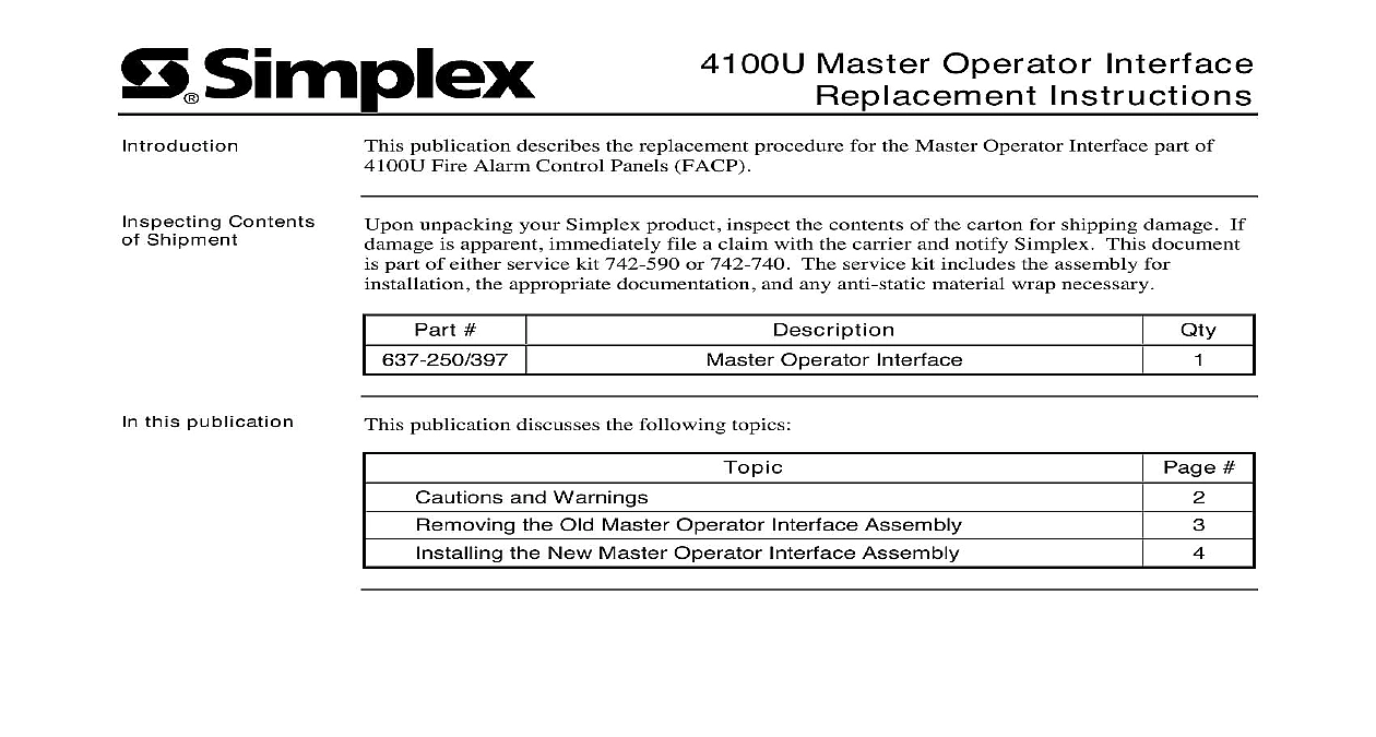
Introduction Contents Shipment Master Operator Interface Instructions publication describes the replacement procedure for the Master Operator Interface part of Fire Alarm Control Panels FACP unpacking your Simplex product inspect the contents of the carton for shipping damage If is apparent immediately file a claim with the carrier and notify Simplex This document part of either service kit 742 590 or 742 740 The service kit includes the assembly for the appropriate documentation and any anti static material wrap necessary Operator Interface this publication publication discusses the following topics and Warnings the Old Master Operator Interface Assembly the New Master Operator Interface Assembly 2001 Simplex Time Recorder Co Westminster MA 01441 0001 USA specifications and other information shown were current as of publication and are subject to change without notice A and Warnings AND SAVE THESE INSTRUCTIONS Follow the instructions in this installation These instructions must be followed to avoid damage to this product and associated Product operation and reliability depends upon proper installation NOT INSTALL ANY SIMPLEX PRODUCT THAT APPEARS DAMAGED Upon your Simplex product inspect the contents of the carton for shipping damage If is apparent immediately file a claim with the carrier and notify Simplex HAZARD Disconnect electrical field power when making any internal or repairs Servicing should be performed by qualified Simplex Representatives HAZARD Static electricity can damage components Therefore handle as follows Ground yourself before opening or installing components use the 553 484 Static Control Prior to installation keep components wrapped in anti static material at all times REACCEPTANCE TEST AFTER SOFTWARE CHANGES To ensure proper operation this product must be tested in accordance with NFPA72 1996 Chapter 7 after programming operation or change in site specific software Reacceptance testing is required any change addition or deletion of system components or after any modification repair or to system hardware or wiring components circuits system operations or software functions known to be affected by a must be 100 tested In addition to ensure that other operations are not inadvertently at least 10 of initiating devices that are not directly affected by the change up to a of 50 devices must also be tested and proper system operation verified the Old Master Operator Interface Assembly Master Operator Interface assembly includes the graphic overlay containing the buttons used interact with the 4100U FACP hence its name However the Master Operator Interface is more than just the display unit and can more generally be referred to as the front door the CPU bay in any 4100U FACP are ribbon cables from the interface assembly connected to the master controller card in the that must be removed before removing the door Other than that replacing the Master Interface involves detaching two grounding straps and unlatching the frame of the door two standoffs extending from the sides of CPU bay Power and the CPU Bay Remove power to the system by disconnecting any battery connection at the PDM and then AC power at the breaker the Old Operator Lower the front door the Master Operator Interface to the CPU bay Remove the two ribbon cables attached to the master controller or CPU daughter card see 1 for the locations of these cables The wider of the two cables is the front display the other is the serial port cable Detach the two green grounding straps connected to studs on the back of the operator assembly by removing the nut and washer from each stud and unhitching the strap door is now connected to the cabinet only by the latches on either side of its frame To completely remove the door press the latches in toward each other and lift the door off the swivel standoffs extending from the side of the bay see Figure 2 the cables here 1 Contents of CPU Bay on next page the New Master Operator Interface Assembly the New Operator Orient the new Master Operator Interface so that the graphic overlay and LCD screen face and the bottom of the assembly is butted against the bottom edge of the CPU bay Press in the latches extending from the sides of the new door frame and hook the door onto swivel screws extending in from the side panels of the bay see Figure 2 Loop the ring at the end of each grounding strap to the corresponding studs extending from back of the door assembly Fasten each strap to the stud with the supplied 8 washer and Connect the serial port and front display ribbon cables extending from the new Master Interface assembly to the appropriate plugs on the master controller or CPU card Again the wider of the two cables is the front display cable the other is the port cable see Figure 1 for the proper locations for these connections 2 Mounting the Master Operator Interface Assembly System for the replacement procedure using the instructions below Close the door to the CPU bay Reapply system power at the breaker Restore battery power to the cabinet by reconnecting the battery cable at the PDM Redress and close the main cabinet door system is now ready for normal operation A