Simplex 4100U Upgrade and Rack Mount Kits - Installation Instructions

File Preview
Click below to download for free
Click below to download for free
File Data
| Name | simplex-4100u-upgrade-and-rack-mount-kits-installation-instructions-6289510347.pdf |
|---|---|
| Type | |
| Size | 1.74 MB |
| Downloads |
Text Preview
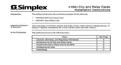
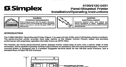
Introduction Contents Shipment this Publication Upgrade and Rack Mount Kits Instructions publication describes the installation procedure for the following Master Controller Upgrade Kit Expansion Bay Upgrade Kit Upgrade Kit for the 4020 Rack Mount Kits unpacking your Simplex product inspect the contents of the carton for shipping damage If is apparent immediately file a claim with the carrier and notify Simplex Page publication discusses the following topics and Warnings the Upgrade Kits Controller Upgrade Kit Installation Bay Upgrade Kit Installation Upgrade Kit Installation the Rack Mount Kits 2001 Simplex Time Recorder Co Westminster MA 01441 0001 USA specifications and other information shown were current as of publication and are subject to change without notice B and Warnings AND SAVE THESE INSTRUCTIONS Follow the instructions in this installation These instructions must be followed to avoid damage to this product and associated Product operation and reliability depends upon proper installation NOT INSTALL ANY SIMPLEX PRODUCT THAT APPEARS DAMAGED Upon your Simplex product inspect the contents of the carton for shipping damage If is apparent immediately file a claim with the carrier and notify Simplex HAZARD Disconnect electrical power when making any internal adjustments repairs Servicing should be performed by qualified Simplex Representatives removing power from this system disconnect batteries first and AC power last When power to the system connect AC power first and batteries last HAZARD Static electricity can damage components Therefore handle as follows Ground yourself before opening or installing components use the 553 484 Static Control Prior to installation keep components wrapped in anti static material at all times the Upgrade Kits 4100 upgrade kits are for customer sites that use older equipment 4020 Fire Systems and older 4100 systems 4100 7150 and 2301 Upgrade Kits are used for customer sites that use non 4100U back PID series 2975 91xx and need to upgrade to the newer 4100 functionality The kits are so that the 2975 91xx back boxes may be used with new Rev 10 hardware When an kit is installed the 4100 system becomes a Rev 10 system 4100 9833 Upgrade Kit is used to connect the 4100U to a 4020 Fire Alarm System which be located nearby Master Kit 4100 7150 Master Controller Upgrade Kit contains the following CPU card This is the new CPU card that must be inserted into the motherboard that is in the cabinet New user interface Harness 734 085 Front panel labels Hardware Kit INTERFACE CARD 4100U 1 Master Controller Upgrade Kit Components on next page the Upgrade Kits Continued Expansion Bay Kit 4100 2301 Expansion Bay Upgrade Kit contains an electronics bay that contains a power interface PDI for mounting new 4 x 5 cards FLAT CARDS CAN MOUNTED TO THE BAY AND SWITCH CAN BE TO THE ASSEMBLY 2 Expansion Bay Upgrade Kit Components 4020 Kit Upgrade Kit for the 4020 is comprised of a 4100U CPU bay in a 2975 94xx Back Box BACK BOX CONTROLLER CONTROLLER AND RETAINER 3 4020 Upgrade Kit Components Controller Upgrade Kit Installation Steps controller upgrade kit installation consists of the following Replacing the old master controller card with the new CPU card Replacing the old operator interface with the new one Wiring the new CPU card to the new operator interface section combines each step into one comprehensive set of instructions and contains which should be reviewed before installation the instructions below to install the master controller upgrade kit The terminal block for in the back box will still be used for power distribution of the power distribution module PDM The PDM is only used in 2975 Back Boxes Open the master controller bay and remove the harness connecting the master controller P2 on the operator interface Remove the master controller daughter card Remove the operator interface Remove any harnesses connecting the operator interface with the interior of the bay There are two headers on the top two corners of the interface that prevent it from Push the two headers outward and swing the interface open Remove the entirely from the bay and set them aside for later Remove the clips from the headers that hold the lower two corners of the interface to bay and then push the two headers outward Remove them entirely from the bay set them aside for later Now you can remove the operator interface on next page Controller Upgrade Kit Installation Continued continued the new upgrade kit master controller daughter card into the slot that was used for the master controller daughter card The connector is keyed so that the daughter card fits only way Before installing the card Attach the three rubber card spacers provided in the shipping group to the side of the CPU board on the upper corners 2 and upper middle of 1 See figure Examine the slot in the motherboard and the fingers on the daughter card and note the key is located Attach the ground wire 616 728 provided in the shipping group with 426 024 and 322 112 nut to the hole located at the bottom right hand corner of the CPU See figure CPU board into master controller daughter card Attach ground wire 616 728 from CPU board to the master controller daughter under its bottom left hand corner mounting screw RUBBER CARD SPACER LOCATIONS to back side of board MODEM CARD AREA WIRE 4 Upgrade Kit Master Controller Daughter Card Secure the upgrade operator interface to the bay Position the holes on the bottom sides of the operator interface with the holes on the front corners of the bay Push the two headers you set aside in step 3 c the aligned bay and operator interface holes Attach the clips to the headers that the headers won slide Swing the operator interface shut so that the holes in the top corners align with the in the front top corners of the bay Push the two headers you set aside in step through the aligned bay and operator interface holes Use a Harness 734 033 to connect P6 on the CPU card to P3 on the operator interface Bay Upgrade Kit Installation bay upgrade kit installation consists of the following Configuring the power distribution interface PDI Replacing an old electronics bay with the new expansion bay Wiring the electrical assembly to the CPU cabinet and or other bays section combines each step into one comprehensive set of instructions This section also general guidelines and information on the power distribution interface PDI which is to expansion cabinets Due to the depth of the box motherboards with daughter cards cannot used in upgrade expansion bays Motherboards should only be over the PDI if a 2975 94xx Back Box is used in which case upgrade kit is not used expansion bays distribute power and data via the power distribution interface PDI The is a wiring board with eight card slots each of which can accommodate a 4 X 5 slave card PDI cannot accommodate motherboards POWER DISTRIBUTION INTERFACE 566 084 4 The Power Distribution Interface PDI PDI can be configured to draw its power from different sources via jumper ports P4 and P5 To draw power from an XPS on the PDI set jumpers on ports P4 and P5 to positions 2 3 To draw power from P1 from the SPS or RPS set jumpers on ports P4 and P5 to 1 and 2 default To remove power from the PDI remove the jumper from port P4 the instructions below to install the expansion bay upgrade kit Locate the electrical assembly that is to be removed Loosen