Simplex 4120 Network Processing Unit (NPU) Installation Instructions

File Preview
Click below to download for free
Click below to download for free
File Data
| Name | simplex-4120-network-processing-unit-npu-installation-instructions-3685247910.pdf |
|---|---|
| Type | |
| Size | 736.45 KB |
| Downloads |
Text Preview
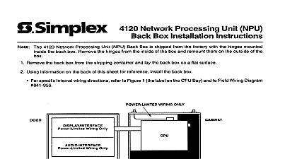
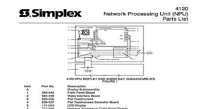
Cautions and Warnings Network Processing Unit NPU Instructions NOT INSTALL ANY SIMPLEX PRODUCT THAT APPEARS Upon unpacking your Simplex product inspect the contents of the for shipping damage If damage is apparent immediately file a claim the carrier and notify Simplex HAZARD Disconnect electrical power when making any adjustments or repairs Servicing should be performed by qualified Representatives 4120 Network Processing Unit NPU consists of a front panel user touchscreen display and a computer case that houses the CPU I O and UL cards The NPU is available with optional voice capabilities publication uses an NPU with voice capability see Figure 1 as an example assumes a back box is installed If the unit comes mounted in a back box the unit in accordance with Pub No 574 020 LISTS ON LOG LOG CONTROL PRINTER CONTROL CONTROL CONTROL INFO CONTROL PRINTER FIRE PRIORITY 2 SYSTEM SYSTEM SIGNALS ALARM ALARM POWER ON PROCESSING UNIT OPERATING INSTRUC TROUBLE INDICATOR FLASHING ACKNOWLEDGE ACK LOCATED UNDER OPERATION UNTIL ALL ARE ACKNOWLEDGED SILENCE ALARM SIGNALS ALARM SILENCE RESTORE SYSTEM TO NORMAL SYSTEM RESET ACK TO SILENCE TONE PERFORM CONTROL FUNCTIOS UTILITY CONTROL DESIRED CONT FUNC ON DISPLAY PANEL FROM KEYBOARD TOUCHSCREEN DISPLAY ALARM ACK ALARM ACK SUPV ACK TBL ACK ALARM SILENCE SYSTEM RESET CONTRAST CONTROL CONTROL TO PAGE ALL AREAS TO SELECT SPEAKERS AUDIO TO ANSWER CALL SELECTIVE TO ANSWER INCOMING CALL ALL SPEAKERS TALK Press AUDIO CONTROL Lift handset Lift handset press ANSWER mic and press switch Use touchscreen display to select Press PHONE CONTROL TO PLACE CALL ON HOLD into mic after the If paging remove microphone and Use touchscreen display to sel Press HOLD Documentation 1 NPU with Voice Capability following is a list of additional documentation that may aid you in the of the NPU Back Box Installation Instructions 574 020 Ferrite Beads with MEDIA Cards 574 041 Network Processing Unit NPU Parts List NET 81 010 Network Concepts NET 91 500 NPU Field Wiring Diagram 841 947 Multiport SLI Option Installation Instructions 574 097 Simplex Time Recorder Co Westminster MA 01441 specifications and other information were current as of publication and are subject to change without notice E Bay Assembly the following steps Tables 1 and 2 and Figure 2 to install the NPU in the box Lay the shipping container on a flat surface near the back box where the is to take place Carefully remove the plastic bands from the container and remove the cover Remove the packing material from the door assembly and the CPU bay Using the hardware provided insert a No 8 mounting screw in both the top and top left support holes of the back box the seated position of each screw in Step 5 Allow the bay to hang from the screws you will them later Tighten the two No 8 mounting screws while leaving an 1 8 inch gap Carefully place the teardrop holes on the CPU bay onto the two screws Using the information in Table 1 securely tighten all mounting screws Make certain that you do not pinch any wiring behind CPU bay when mounting as damage may occur to equipment the remaining mounting screws through the screw holes in the bay 1 Recommended Torque for NPU Mounting Hardware Size 6 8 10 Torque to 8.7 inch ounces to 17.8 inch ounces to 29.7 inch ounces door hinges are mounted backwards to protect material during shipping installing the door assembly remove the hinges and re install them in the position The door assembly may require two people to install Follow 1 through 3 to install the door assembly Line up the top hinge with the door slot and place the hinge pin into the leaving enough play to line up bottom hinge on next page Continued Assembly continued Line up bottom hinge and gently drive home both hinge pins there are any remaining hinges line up hinges and gently drive home the hinge pins the CPU bay cover Use the information in Table 2 and Figure 2 to the connectors from the door assembly to the CPU bay Refer to the Field Wiring Diagram supplied for information on connecting AC I O Local Phone Microphone Speaker and Network wiring 2 Door Assembly to CPU Bay Cable Terminations Part Number Assembly Termination Bay Termination Front Panel Board 565 442 P2 Interface Board 565 496 P2 Screen Controller P2 I O Board Slot 1 P4 Board Slot 2 J13 Board Slot 2 J12 Assembly Bay Bay Optional Front Panel Interface Board I O 2 Door Assembly to CPU Bay Installation 2120 BMUXs Using RS232 Media Cards on UL I O Board Requirements the SLI Option section describes how to connect two or less 2120 BMUXs to an NPU the RS 232 Media Cards on the UL I O Board 565 283 The UL board supplied with every NPU You must have Version 2.01 or later NPU to install a Serial Line Interface SLI To connect 2120 BMUXs using the SLI Multiport card to configure NPU software and to use the 2120 Point Collection Utility refer to Multiport Option Installation Instructions 574 097 3 lists the required hardware to complete the installation Figure 3 how to connect the necessary hardware from the computer port on 2120 BMUX to the RS 232 Media Card on the UL I O board 3 Hardware for NPU Installation Number Media Card with Male Terminal Block Female Terminal Block Plug Assembly RS232 suppressor Steps 1 through 5 to install the SLI option to a 2120 BMUX For information refer to the SLI Multiport Option Installation 574 097 Ensure that the power is OFF before starting this procedure Complete all wiring according to the wiring diagram shown in Figure 3 Connect the five position female terminal block 450 457 to the male block TB1 on the RS 232 Media Card 565 327 Connect the DB25 male connector 733 572 to the computer port on the Complete Steps 1 through 4 for each 2120 BMUX you are connecting two BMUX maximum on next page 2120 BMUXs Using RS232 Media Cards on UL I O Board with Adapter Cable continued After connecting the BMUX s to the CPU see Figure 3 for detailed turn the power ON The CPU automatically boots up to the program screen 3 Connecting 2120 BMUXs to the RS232 Media Card in the NPU the CPU Board to document 579 227 for information on upgrading the NPU CPU E


