Simplex 4120 NPU CPU Replacement Installation Instructions
File Preview
Click below to download for free
Click below to download for free
File Data
| Name | simplex-4120-npu-cpu-replacement-installation-instructions-1736958240.pdf |
|---|---|
| Type | |
| Size | 4.16 MB |
| Downloads |
Text Preview
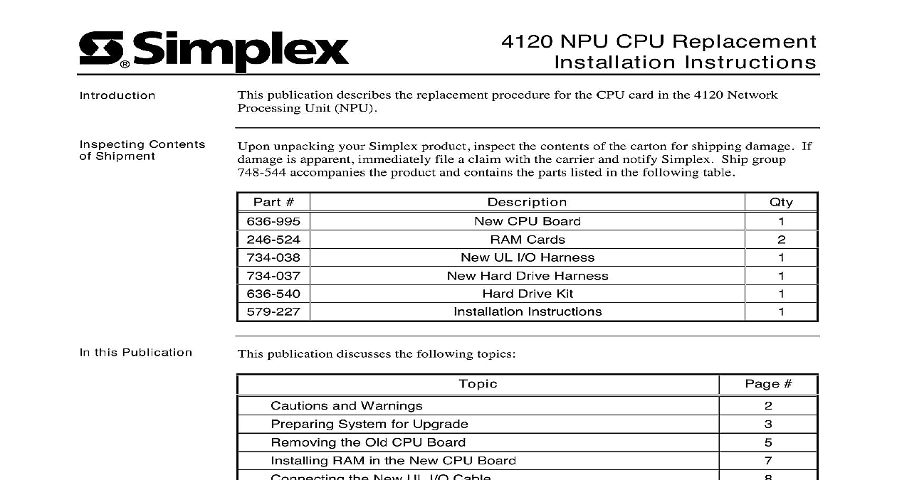
Introduction Contents Shipment NPU CPU Replacement Instructions publication describes the replacement procedure for the CPU card in the 4120 Network Unit NPU unpacking your Simplex product inspect the contents of the carton for shipping damage If is apparent immediately file a claim with the carrier and notify Simplex Ship group accompanies the product and contains the parts listed in the following table this Publication publication discusses the following topics CPU Board Cards UL I O Harness Hard Drive Harness Drive Kit Instructions and Warnings System for Upgrade the Old CPU Board RAM in the New CPU Board the New UL I O Cable the New CPU Board the Hard Drive up the System for Reconfiguration CMOS Setup from a 636 588 CPU Board 2000 Simplex Time Recorder Co Westminster MA 01441 0001 USA specifications and other information shown were current as of publication and are subject to change without notice A and Warnings AND SAVE THESE INSTRUCTIONS Follow the instructions in this installation These instructions must be followed to avoid damage to this product and associated Product operation and reliability depends upon proper installation NOT INSTALL ANY SIMPLEX PRODUCT THAT APPEARS DAMAGED Upon your Simplex product inspect the contents of the carton for shipping damage If is apparent immediately file a claim with the carrier and notify Simplex HAZARD Disconnect electrical field power when making any internal or repairs Servicing should be performed by qualified Simplex Representatives HAZARD Static electricity can damage components Therefore handle as follows Ground yourself before opening or installing components use the 553 484 Static Control Prior to installation keep components wrapped in anti static material at all times SAFETY HAZARD Under certain fiber optic application conditions the optical output of device may exceed eye safety limits Do not use magnification such as a microscope or other equipment when viewing the output of this device FREQUENCY ENERGY This equipment generates uses and can radiate radio energy and if not installed and used in accordance with the instruction manual may interference to radio communications It has been tested and found to comply with the for a Class A computing device pursuant to Subpart J of Part 15 of FCC Rules which are to provide reasonable protection against such interference when operated in a environment Operation of this equipment in a residential area may cause interference which case the user at his own expense will be required to take whatever measures may be to correct the interference REACCEPTANCE TEST AFTER SOFTWARE CHANGES To ensure proper operation this product must be tested in accordance with NFPA72 1996 Chapter 7 after programming operation or change in site specific software Reacceptance testing is required any change addition or deletion of system components or after any modification repair or to system hardware or wiring components circuits system operations or software functions known to be affected by a must be 100 tested In addition to ensure that other operations are not inadvertently at least 10 of initiating devices that are not directly affected by the change up to a of 50 devices must also be tested and proper system operation verified System for Upgrade System Backup the network original CPU board in the 4120 NPU was part number 636 588 386SX microprocessor then there has been a replacement board the 636 802 486DX2 microprocessor This describes the procedure for a new upgrade The new board is part number 636 995 manual focuses mostly on an upgrade from a 636 802 to a 636 995 There are also contained for upgrading from a 636 588 to a 636 995 you are upgrading from a 636 802 to a 636 995 proceed with the instructions below and the section entitled from a 636 588 CPU Board at the end of this you will be upgrading from a 636 588 to a 636 995 see the section entitled a 636 588 CPU Board a blank floppy diskette into the floppy drive From the DOS prompt type a s to make a system diskette Copy FDISK EXE FORMAT COM and SYS COM from the DOS directory to your floppy From the CMOS setup write down the hard drive settings including the size type sectors Disconnect the panel batteries at the fuse Disconnect AC power at the breaker all Ribbon on the CPU Remove the front cover on the chassis inside the main cabinet by removing the four T15 Torx located at its corners Locate the CPU board within the chassis It the vertically oriented board second from the Most of the ribbon cables in the case will be connected to it of the CPU within the Case 1 Contents of Chassis on next page System for Upgrade Continued all Ribbon on the CPU continued Label the ribbon cables attached to the CPU board up the position of each cable on the board with Figure 2 and use the labels suggested in callouts You will use these labels later when you connect the cables to the new CPU A B Drive Drive I O 2 Labels for Connections on the Old CPU Board the Old CPU Board Cables the CPU Board attached at this time Disconnect from the CPU board the cables you have labeled Leave the other ends of the Remove the other end of the cable you labeled drive This end is attached to the hard located in the drive assembly see Figure 8 at the bottom right of the chassis This can be discarded as you will be replacing it later Cables the UL I O Locate the UL I O card It is the card installed in the leftmost position of the chassis to the left of the CPU board you are replacing Remove the ribbon cable from the position on the UL I O card shown in Figure 3 The end of this cable should remain attached to the green box at the top of the chassis the Attached the I O Labeled Here and 3 UL I O Board Remove the cable you labeled I O from the UL I O board The position of this cable is in Figure 3 This cable can be discarded as you will be replacing it later on next page the Old CPU Board Continued the Old Board Using a T15 size Torx screwdriver remove the screw at the top edge of the CPU board This the screw that fastens the board to the edge of the chassis Pull the board straight out of the case following along the guides at the bottom of the case It take some force to initially detach the edge of the board from the bus connection in the of the case RAM in the New CPU Board the RAM into New Board need to attach the two RAM cards 246 524 supplied in the ship group to the new CPU There are four RAM locations on the new card and the RAM must be installed in slots In other words the cards go in either the first and third slots or the second and slots Figure 4 shows the RAM slots on the new board 4 Alternating RAM Slots each card by inserting the bottom of the card beneath the small gold pins extending from the base of the RAM housing To do this hold the RAM at a 45 angle Step one in Figure 5 The card will only fit in one way There should be a key or notch in the bottom it that lets you know which side enters the base This notch will also only fit the slot when the RAM card is facing the correct direction 2 1 5 RAM Insertion Once you have the card positioned correctly ro