Simplex 4190-9013 Remote Printer Installation Instructions
File Preview
Click below to download for free
Click below to download for free
File Data
| Name | simplex-4190-9013-remote-printer-installation-instructions-1693280574.pdf |
|---|---|
| Type | |
| Size | 714.91 KB |
| Downloads |
Text Preview
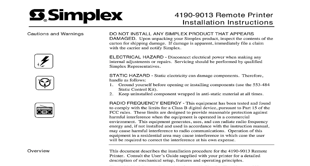
Cautions and Warnings Remote Printer Instructions NOT INSTALL ANY SIMPLEX PRODUCT THAT APPEARS Upon unpacking your Simplex product inspect the contents of the for shipping damage If damage is apparent immediately file a claim the carrier and notify Simplex HAZARD Disconnect electrical power when making any adjustments or repairs Servicing should be performed by qualified Representatives HAZARD Static electricity can damage components Therefore as follows Ground yourself before opening or installing components use the 553 484 Control Kit Keep uninstalled component wrapped in anti static material at all times FREQUENCY ENERGY This equipment has been tested and found comply with the limits for a Class B digital device pursuant to Part 15 of the rules These limits are designed to provide reasonable protection against interference when the equipment is operated in a commercial This equipment generates uses and can radiate radio frequency and if not installed and used in accordance with the instruction manual cause harmful interference to radio communications Operation of this in a residential area may cause interference in which case the user be required to correct the interference at his own expense document describes the installation procedure for the 4190 9013 Remote Consult the User Guide supplied with your printer for a detailed of mechanical setup features and operating principles 4190 9013 Remote Printer interfaces with Simplex Fire Alarm and Nurse systems The printer provides hard copy of status reports for these systems Fire Alarm Multiplex Nurse Call Network GCC NPU Printer Default Settings Interface DIP Switches Connections to Fire Alarm Systems Front Panel Programming for an RS 232 Port to 5001 Nurse Call Panel Buttons and Lights Number A This Publication following topics are covered in this publication 2000 Simplex Time Recorder Co Westminster MA 01441 0001 USA specifications and other information shown were current as of publication and are subject to change without notice Printer s Default Settings you can often set the default settings through your application software or driver you may need to change a default setting from the printer s control using the default setting mode Table 1 below lists the default settings in and options you can select in this mode 1 Printer Settings length for tractor over perforation tear off line feed direction slash speed draft mode I F wait time I F bi directional mode mode CR IBM 2390 Plus IBM 2390 Plus table in inches 3 3.5 4 5.5 6 7 8 8.5 11 70 6 12 14 17 Off Off Off Uni D Auto IBM 2390 Plus Off Parallel Optional seconds 30 seconds Off Off Off Off model PC 437 PC 850 PC 861 BRASCII Roman 8 ISO Latin 1 858 ISO 8859 15 other models Italic PC 437 850 PC 437 Greek PC 853 855 PC 852 PC 857 PC 864 866 PC 869 MAZOWIA MJK ISO 8859 7 ISO Latin 1T PC 774 Estonia 8859 2 PC 866 LAT PC 866 UKR APTEC PC 708 PC 720 AR864 PC 860 PC863 PC 864 861 BRASCII Abicomp 8 ISO Latin 1 PC 858 8859 15 PC 771 U S A Italic France Italic Italic U K Italic Denmark1 Sweden Italic Italy Italic Spain1 Orator S Script C T Sans Serif H second 1.5 seconds seconds 3 seconds Off Off character set for table Feed wait time paper settings take effect only when IBM 2390 Plus emulation is selected Printer s Default Settings Continued Default Settings the steps below to enter the default setting mode and change the printer s settings To print the language selection and default setting mode instructions need 5 sheets of letter or A4 size single sheet paper or 5 pages of paper If you use single sheets you need to load a new each time the printer ejects a printed sheet Make sure paper is loaded and the printer is turned off Whenever you turn off the printer wait at least 5 seconds turning it back on otherwise you may damage the While holding down the Font button turn on the printer The printer enters default setting mode and prints the language selection instructions you need to select a different language press the Font button until the lights indicate the language you want as described in the language instructions Press the Tear Off Bin button to confirm your language selection and print current default settings you do not need to change any settings go to step 6 If you want to any of the default settings press the Tear Off Bin button to print the three pages in the language you selected Follow these instructions to change the default settings using the buttons on printer control panel The arrows on the instruction sheets indicate the printer s current When you finish turn off the printer and exit the default setting mode The settings remain in effect until you change them again Interface DIP Switches serial interface card enables communication between the 4190 9013 Remote and a host computer see Figure 2 for the location of the serial interface serial interface card has two sets of DIP switches see Figure 1 You interface operations by adjusting the switch settings You can access DIP Switch 1 and adjust settings as needed even after the interface card DIP Switch 2 is not readily accessible after installation Therefore make necessary adjustments to DIP Switch 2 before installing the serial card section describes the DIP switch settings for operation with compatible Fire systems Refer to the Serial Interface Card manual provided with the interface card for detailed information on serial interface card installation DIP 1 DIP 2 1 Serial Interface Card DIP Switches on next page Interface DIP Switches Continued Interface Switch 1 2 defines the serial interface settings for DIP Switch 1 2 DIP Switch 1 Settings parity 4010 odd or no 2120 4010 GCC NPU Check 1 4120 and Card Word Length Check 2 both even 4020 odd parity GCC NPU even parity 4100 both 1200 baud 4020 4120 and baud 4010 GCC NPU Rate 1 both 1200 baud 4020 4120 and 9600 baud 4120 GCC NPU Rate 2 Units must be set for NO parity at 1200 baud on next page Interface DIP Switches Continued Interface Card Switch 2 3 defines the settings for DIP Switch 2 3 DIP Switch 2 Settings both 1200 baud 4020 4100 and 9600 4010 4120 4120 NPU 9600 baud rate 4120 GCC NPU Rate 3 Rate 4 Loop 1200 rate 4020 4120 Loop Unit to be set for 1200 baud Connections Ports following sections illustrate the connections between the 4190 9013 Remote and the various host systems Fire Alarm or Nurse Call with which it is the port on the serial interface card for conn