Simplex 4190-9826, 4190-9827 Fire Alarm Network Products, Network System Integrator (A)

File Preview
Click below to download for free
Click below to download for free
File Data
| Name | simplex-4190-9826-4190-9827-fire-alarm-network-products-network-system-integrator-a-9280174356.pdf |
|---|---|
| Type | |
| Size | 691.62 KB |
| Downloads |
Text Preview
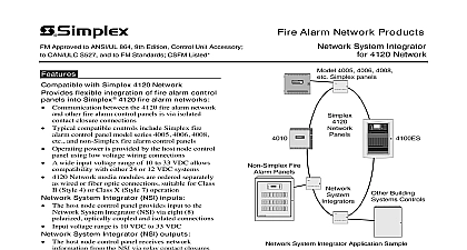
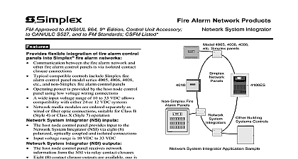
Approved to ANSI UL 864 9th Edition Control Unit Accessory CAN ULC S527 and to FM Standards CSFM Listed Alarm Network Products System Integrator flexible integration of fire alarm control into Simplex fire alarm networks Communication between the fire alarm network and fire alarm control panels is via isolated contact connections Typical compatible controls include Simplex fire control panel model series 4005 4006 4008 and non Simplex fire alarm control panels Operating power is provided by the host node control using low voltage wiring connections A wide input voltage range of 10 to 33 VDC allows with either 24 or 12 VDC systems Network media modules are ordered separately as or fiber optic connections suitable for Class B 4 or Class X Style 7 operation System Integrator NSI inputs The host node control panel provides input to the System Integrator NSI via eight 8 optically coupled and isolated connections voltage range is 10 VDC to 33 VDC System Integrator NSI outputs The host node control panel receives network from the NSI via relay contact closures Eight 8 contact closure outputs are available one is as the trouble contact Output 2 the other are system programmable per application Output 1 has dual contacts Outputs 2 8 are single each selectable as N O or N C Contacts are rated 1 A 24VDC 25 VAC and A 70 VAC packaging Small 13 square 343 mm cabinet size allows mounting Available with beige or red cabinet mode A technician activated network bypass mode is with temporary battery connection to allow service of the host node control with the remaining on line to maintain network information FM tested and approved to UL Standard 864 9th and NFPA 72 the National Fire Alarm and Code for connection to agency fire alarm control panel Due to the NSI input and output design the NSI is capable of compatibility with other building controls including products used for Communications Systems ECS Mass subject to local authority having AHJ 4005 4006 4008 Simplex panels E TE M PERVIS ORY YST EM OUBLE AR M NCE D OW ER LAR M UPV CK OU BLE K ARM E YST EM REV IOUS NU XT NABLE UNCT ION R CT AND C P OWER ERVICING SYSTEM INTEGRATOR 2 0 2 1 5 p m A E M B L E Y E S N O R M AL SY S T E M M C E D O T E M V I Y P E Y S R O O R L A E M M o n 8 M a r 9 9 L A C M U P C K R O C K L E A E M Y C E E T E M I R E AL A R M O NT R O L I O N I O E O N E T V R I F G Fire Panels SYSTEM INTEGRATOR Building Controls SYSTEM INTEGRATOR System Integrator Application Sample Network System Integrators NSI provide a between a fire alarm control panel and a Simplex alarm network This allows the network to monitor inputs from and provide contact closure to host node control panels not equipped for network communications The integrated control with NSI resides as a unique node on the fire alarm NSI power input voltages contact voltages and battery backup are supplied by the node control NSI network connections are similar to network products using a and port by plug in media cards either wired or fiber Class B or Class X operation to the NSI Information is received by the from the host node panel via eight optically isolated capable of receiving 10 to 33 VDC from the host Since each input is optically isolated the source of control can be either relay contact or transistor circuits and inputs can be from different sources This product was tested and approved by FM Approvals against standard FM testing to NFPA 72 ANSI UL Standard 864 9th Edition and CAN ULC S527 This has been approved by the California State Fire Marshal CSFM pursuant to Section of the California Health and Safety Code See CSFM Listing 7300 0026 329 for values and or conditions concerning material presented in this document It is to re examination revision and possible cancellation Additional listings may be contact your local Simplex product supplier for the latest status Listings and under Simplex Time Recorder Co are the property of Tyco Fire Protection 4 2012 Description Continued Information from the NSI Information is transferred the NSI to the host node panel using eight relay Relay 2 is dedicated to advise the host node of an NSI trouble and is held normally energized of power to the NSI or other onboard NSI trouble transfer the trouble contact The remaining seven functions are programmable at the NSI connections between the NSI and the host node panel are not supervised by the NSI Considerations Supervision of wiring if provided is supplied by the host node panel For applications where connections are not mount the NSI close nippled to the host node panel within 20 ft 6 m Mode For authorized service operation the NSI provided with an optional battery input allowing the loop to remain intact when the host node panel is for servicing The NSI does not provide to this service battery connection Normal battery is provided by the host node control panel Information For additional information to Installation Instructions 579 876 Product Selection Cabinet Cabinet System Integrator cabinet assembly order network media cards separately below Wired media module optic media module two media modules operation as required Specifications Power to NSI Host Control from to Host Control Connection to Installation 579 876 additional TSP twisted pair twisted pair Specifications Range Voltage Range 10 VDC to 33 VDC 3.5 W maximum 12 VDC input 300 mA maximum input current 10 VDC 24 VDC input 175 mA maximum input current 20 VDC type 8 optically isolated inputs voltage range 10 to 33 VDC voltage supplied by host node control panel or other compatible voltage requirements 1 mA minimum required for activation input resistance 9.5 k Details 8 contact closure outputs Contact 1 provides dual connections Contacts 2 8 single connections Contact 2 is dedicated as Trouble Indication each contact is jumper selectable as N O or N C Ratings 1 A 24 VDC or 25 VAC 0.5 A 70.7 VAC resistive supply current protection externally listed in line fuse and fuseholder or equivalent current limiting to contact ratings Connections Between Host Control Panel and NSI Connection Wiring terminals 18 to 14 AWG 0.82 mm2 to 2.08 mm2 optics or wired wired connection terminals for 24 AWG to 18 AWG mm2 to 0.82 mm2 Parameter Network line to line capacitance distance 57,600 bps distance 9600 bps 18 AWG TSP pF ft 190 pF m ft 3 km ft 5.18 km Type Margin Optic dB dB dB dB dB dB dB dB 24 AWG TP pF ft 72 pF m ft 2.13 km ft 3.65 km Distance ft 3 km ft 4.57 km ft 3.96 km ft 4.57 km W x 13