Simplex 4603-9101 LCD Annunciator ™ Installation Instructions

File Preview
Click below to download for free
Click below to download for free
File Data
| Name | simplex-4603-9101-lcd-annunciator-installation-instructions-0187256934.pdf |
|---|---|
| Type | |
| Size | 727.37 KB |
| Downloads |
Text Preview
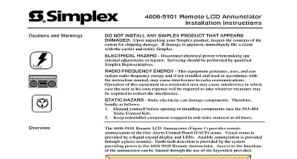
Cautions and Warnings Annunciator Instructions NOT INSTALL ANY SIMPLEX PRODUCT THAT APPEARS Upon unpacking your Simplex product inspect the contents of the for shipping damage If damage is apparent immediately file a claim the carrier and notify Simplex HAZARD Disconnect electrical power when making any adjustments or repairs Servicing should be performed by qualified Representatives HAZARD Static electricity can damage components Therefore as follows Ground yourself before opening or installing components use the 553 484 Control Kit Keep uninstalled component wrapped in anti static material at all times are several important notes to identify before installing the 4603 9101 Annunciator All circuits are power limited only if the operating and communications are provided by a 4020 Unit or by a system with the 4100 4120 6050 option If other systems are used no are power limited 4603 9101 LCD Annunciators can be either flush or surface mounted To flush mount in masonry walls use a RACO 965 3 1 2 in deep box or its equivalent To flush mount in plasterboard walls use a RACO 590 3 1 2 in deep switch box with conduit entry or its equivalent Conduit entry must be centered 2 3 4 in minimum the front of the box To surface mount use a 2975 9206 Box The number of annunciators in a 4100 Fire Alarm System cannot exceed 31 The maximum operating current for a single 4603 9101 LCD Annunciator is mA Do not use the 4603 9101 LCD Annunciator when the 4100 Control Panel configured for proprietary receiving service An Earth ground connection must be provided to the box for transient suppression This connection be made with an approved dedicated Earth in accordance with NFPA 70 Article 250 1999 Simplex Time Recorder Co Gardner MA 01441 0001 USA specifications and other information shown were current as of publication and are subject to change without notice B Instructions Steps 1 through 5 and refer to Figures 1 through 3 to install a LCD Annunciator Terminate the annunciator COMM and power lines as shown in Figure 1 Field Wiring Diagram 841 731 for additional details 1 Terminating the COMM and Power Lines Using Switch SW1 see Figure 2 set the annunciator address and baud in accordance with Chart 1 Switches SW1 2 through SW1 8 set the annunciator address SW1 1 sets the annunciator baud rate OFF or OPEN 1200 Baud ON or CLOSED 9600 Baud Using the two pan head screws provided mount the annunciator in its back Using the four flat head screws provided mount the trim plate to the back in accordance with Figure 3 in accordance with Figure 3 The trim plate covers a hole in the keyboard which provides access to the viewing angle potentiometer Call your local Simplex Branch Office listed in the yellow pages for on next page Instructions to Figure 2 for the terminal block locations on the LCD Annunciator to Figure 3 for a detailed picture of the annunciator Assembly 2 Plate 2 Terminal Block Locations of LCD Annunciator Box Head Screws 4 The annunciator back box is supplied by Simplex See 1 in the Overview section this publication for a list of back boxes Back box Earth ground is required 3 Expanded View of 4603 9101 LCD Annunciator Chart 1 2 3 4 5 6 7 8 9 10 11 12 13 14 15 16 17 18 19 20 21 22 23 24 25 26 27 28 29 30 31 32 33 34 35 36 37 38 39 40 41 42 43 44 45 46 47 48 49 50 51 52 53 54 55 56 57 58 59 60 61 62 63 64 65 66 67 68 69 70 71 72 73 74 75 76 77 78 79 SW1 Addresses 1 thru 119 set for address 13 and 9600 baud 8 Shown OFF Position OPEN CLOSED 1 Shown ON Position Rate OPEN CLOSED 1200 BAUD 9600 BAUD 3 80 8