Simplex 4606-9102, 4603-9111, 2975-9206 4606-9102 LCD Annunciator for 4010ES Fire Alarm Control Panels

File Preview
Click below to download for free
Click below to download for free
File Data
| Name | simplex-4606-9102-4603-9111-2975-9206-4606-9102-lcd-annunciator-for-4010es-fire-alarm-control-panels-0517296483.pdf |
|---|---|
| Type | |
| Size | 748.91 KB |
| Downloads |
Text Preview
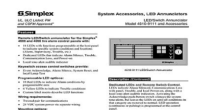
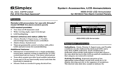
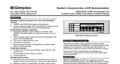
ULC CSFM Listed NYC Fire Dept Approved Accessories LCD Annunciators 4606 9102 LCD Annunciator 4010ES Fire Alarm Control Panels LCD annunciator for use with Simplex 4010ES fire alarm control panels readout provides Two lines of 40 characters each Wide viewing angle super twist design LED backlighting switches and status LEDs for Alarm Priority 2 Supervisory or Trouble keyswitch access controlled Alarm silence System reset Three programmable control switches with yellow and provisions for custom labeling features is transmitted over a single unshielded pair separate wiring is required for 24 VDC panel power see p 3 for more information Tone alert sounder provides local audible indication Lamp and LCD are functionally tested each time the is turned on Mounts flush on standard 6 gang electrical box Up to up to 20 internal and external card addresses per fire alarm control panel and trim options ordered separately page 3 for more details Surface mount box model 2975 9206 Brushed stainless steel trim model 4603 9111 Annunciation 4606 9102 LCD Annunciator 4010ES fire alarm control panels to provide and control switches at convenient locations from the control panel The LCD is an 80 character alphanumeric display with information presented clear and descriptive English Typical content includes status alarm trouble etc alarm type smoke manual station etc number of system alarms conditions troubles and custom location up to 40 characters long Data communications require a unshielded twisted pair that supports other on the same communications channel LCD Annunciator Continued Alarm Priority 2 Supervisory and Trouble are also indicated by dedicated LEDs and a audible indication Each condition has a acknowledge push button switch that silences tone alert but leaves the LED on until all conditions in category are restored to normal Scrolling Repeated operation of the acknowledge switch will scroll the LCD showing activity in the sequence of occurrence internal tone alert also sounds to indicate the of any of the push button switches Access All switches on the annunciator are by the keyswitch with a key that is only in the disabled position A brief test is performed whenever the keyswitch is from enabled to disabled Operations When enabled notification can be deactivated by pressing the switch Pressing the RESET restores the system to normal operation When activity is normal the LCD displays the time and IS NORMAL This product has been approved by the California State Fire Marshal CSFM pursuant to 13144.1 of the California Health and Safety Code See CSFM Listing for allowable values and or conditions concerning material presented in document It is subject to re examination revision and possible cancellation NYC Fire COA 6095 Additional listings may be applicable contact your local Simplex product for the latest status Listings and approvals under Simplex Time Recorder Co are property of Tyco Fire Protection Products 8 2012 Product Selection Remote LCD Annunciator with beige trim for use with 4010ES fire control panels Brushed stainless steel trim option Matching surface mount box ivory finish Overvoltage protector required where annunciator communications and power wiring exits and enters a refer to data sheet S2081 0016 for details to specifications on page 3 additional details 4606 9102 Operator Information X 40 LCD READOUT green LED during normal conditions abnormal operating conditions STATUS INDICATOR LEDs provide system status in addition to LCD information LEDs flash to the condition and then when acknowledged on steady until reset Fire Alarm and Priority 2 are red System Supervisory System Trouble Alarm Silenced are yellow Power On is green PROGRAMMABLE Yellow each with pushbutton switch and labeling pocket 2 TIME time of last of event being displayed displays current when viewing status ACK FIRE ALARM acknowledges Fire Alarm condition and silences the and all annunciator tone alerts ACK PRIORITY 2 acknowledges Priority 2 Alarm condition and silences panel and all annunciator tone alerts ACK acknowledges System conditions and silences the and all annunciator tone alerts RESET restores panel to normal all alarmed inputs returned to normal ENABLE all switch functions is removable only in position ACK acknowledges Troubles and silences the and all annunciator tone alerts SILENCE causes audible appliances to be silenced after evacuation is complete and alarm source is being investigated 8 2012 4606 9102 LCD Annunciator Specifications Operating Specifications refer to Installation Instructions 579 977 for additional information Operating Current to 32 VDC system supplied mA with LED backlighting on mA during battery backup LED backlighting is turned off after 30 seconds switch activity mA maximum LED backlighting is on and tone alert is sounding to 120 F 0 to 49 C to 93 RH non condensing at 100 F 38 C Standby Current Current Temperature Range Humidity Range RUI Remote Unit Interface external annunciator communications line SLC line circuit Up to 20 total internal and external card addresses 4010ES Panels Requirements Wiring Type Unshielded twisted pair UTP 18 AWG 0.82 mm2 for most applications see below Characteristics 0.58 580 nF maximum capacitance between conductors 35 maximum total resistance Wiring that leaves the building Also requires Isolated Loop Circuit Protectors on Data Applications Shielded Pair STP end refer to data sheet S2081 0007 for 2081 9027 200 mA or for 2081 9028 5 A Wiring run in 500 ft 152 m or more of conduit Wiring closely bundled with standard IDNet communications or TrueAlert communications not required when run with IDNet B wiring Up to 10,000 ft 3048 m total wiring up to 2500 ft 762 m to farthest device X wiring distance Up to 2500 ft 762 m Wiring Wiring Information Dimensions Depth Trim Finish Optional Trim to 12 AWG 0.82 mm2 to 3.31 mm2 wires for 24 VDC system power dedicated earth ground connection to the electrical box is required for proper ESD EMI protection wire in accordance with NFPA 70 National Electrical Code 250 H x 11 13 W 114 mm x 300 mm 5 33 mm 1 at terminal block location 38 mm painted beige stainless steel ordered separately supplied with both slotted and tamper screws boxes Six gang box RACO 965 3 89 mm deep or equal gang boxes Six single gang boxes 3 89 mm deep minimum RACO 590 or equal selection note Conduit entrance is box dependent refer to Installation Instructions 579 977 for mounting information and conduit entry requirements for Surface Mount Box Option ordered separately W x 4 H x 2 D 305 mm x 117 mm x 70 mm steel ivory finish Refer to the 4010ES control panel data sheet for additional panel information 8 2012 Review box choice with assembly layout before selecting conduit entrance