Simplex 4901 Electronic Horn and 4903 Horn-Visible Units – Installation Instructions

File Preview
Click below to download for free
Click below to download for free
File Data
| Name | simplex-4901-electronic-horn-and-4903-horn-visible-units-installation-instructions-2406895137.pdf |
|---|---|
| Type | |
| Size | 816.34 KB |
| Downloads |
Text Preview
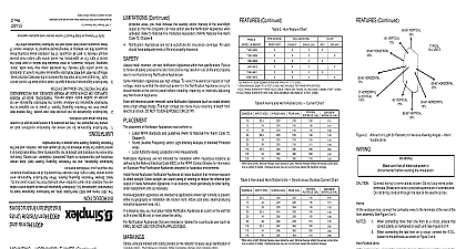
and are subject to change without notice specifications and other information shown were current as of publication Rev A 1997 Simplex Time Recorder Co 574 344 Continued Notification Appliances are not a substitute for insurance coverage All users NUMBERS VERT following an 8 digit Product ID number denotes humid application appliance occupants cannot hear and or see the Notification Appliances within the that are sleeping or hearing visually impaired for whatever reason If intensity to alert all occupants of the protected areas including those or light For all applications the sound and or light output must provide furniture insulation or other obstacles that reduce or even block the sound and or light intensity the protected areas may have walls doors the 4901 and 4903 Notification Appliances meet the current UL standards The output level must meet the requirements of the intended protected areas Appliances provide a specific rated output level of sound and or THE PROTECTIVE SIGNALING SYSTEM OR OTHER BACK UP POWER SOURCES ARE RECOMMENDED an audible and or visible warning THEREFORE BACK UP POWER Appliances for whatever reason the Notification Appliances will not from the Protective Signaling System If power is not supplied to the Appliances do not provide their own power They receive their does sense such conditions fire explosion etc they are activated by a control panel as part of a system Appliances do not sense any hazardous conditions such as Signaling System have access to this information location for future reference so that all people who use maintain and test the know the limitations and adhere to the requirements keep these instructions at a and requirements for safety placement installation and testing Since you Appliances and the Protective Signaling System itself have certain requires your immediate attention and or flash a light they indicate the possibility of an emergency situation Simplex Protective Signaling System When Notification Appliances emit indication of an alarm condition when activated from the control panel of a UL Laboratories UL Notification Appliances provide an audible and or visible 4901 Horns and 4903 Horn Visible Units are Notification Appliances listed by Instructions Horn Visible Units Electronic Horn and When sizing a NAC Nominal Average values should be used Nominal Average reflects the average current draw a number of strobes Individual devices may vary but will never exceed the maximum Average Units 2 Amount of Light In Percent for Various Viewing Angles Horn 5 Synchronous Strobe Units Current Chart VDC mA mA mA mA sure that all electrical power is before starting the installation Continued 3 Horn Feature Chart ID MARKING HORN WITH ONE TONE 25mA MAXIMUM AND 85dBA AT 10 FEET 3.05M 4 Horn Visible Units Current Chart VDC mA mA mA mA Units When sizing a NAC Nominal Average values should be used Nominal Average reflects the average current draw a number of strobes Individual devices may vary but will never exceed the maximum Average TABLE 2 MODEL NUMBERS TABLE 2 MODEL NUMBERS areas you must increase the quantity and or intensity of the sound light so that the occupants can hear and or see the Notification Appliances when Refer to National Fire Protection Association NFPA National Fire Alarm 72 Chapter 6 have adequate levels of life and property insurance install maintain and test Notification Appliances within their specifications Failure follow all safety precautions and instructions may result in loss of life and property to non functioning Notification Appliances Notification Appliances use high voltage To avoid the electrical hazard of high make sure that the electrical power for the Notification Appliance circuit is at the control panel before installing repairing or internally adjusting Notification Appliance with electrical power removed some Notification Appliances such as visible strobes a high voltage charge The high voltage can cause injury resulting in death from shock DO NOT TOUCH EXPOSED CIRCUITRY placement of Notification Appliances must conform to Latest NFPA standards and guidelines Refer to National Fire Alarm Code 72 Sound Audible Frequency and or Light Intensity Analysis of Intended Protected 6 Local Authority Having Jurisdiction AHJ Requirements Appliances are not intended for installation within hazardous locations as by the National Electrical Code NEC or the NFPA Contact Simplex for information Explosion Proof Notification Appliances designed for hazardous environments Humid Application Notification Appliances at indoor locations that minimize exposure direct sunlight Direct sunlight can cause fading of lettering or reduce the effective light of Visible Notification Appliances In all locations check periodically for letter fading replacement units as necessary appliances are intended for applications where high humidity is present by geography or installation site locker room indoor pool area steam producing equipment area etc a sleeping area you must place Visible Notification Appliances at a point on the wall that 24 inches 60.96 cm or more below the ceiling Notification Appliances that are intended or labeled for a particular use such as DO NOT USE FOR OTHER APPLICATIONS units are marked with coding stickers on the reflector for easy visual identification of rating The following candela Table correlates sticker and candela rating 1 Strobe Unit Coding Stickers RATING Asterisk Circle Triangle ID FLASH REQUIRES USE OF 4905 9914 OR 4905 9922 SYNC CUBE SEE PAGE 5 UNDER NORMAL CONDITIONS ALL MODELS RATED AT 15CD PER UL 1971 HAVE BEEN TESTED FOR 75CD ON AXIS ALL 30CD MODELS PER UL 1971 HAVE BEEN TESTED FOR 110CD ON AXIS 2 1Hz Horn Visible Units 60 Flashes Per Minute Maximum Feature Chart CD MARKING TABLE 3 MODEL NUMBERS 1 Horns and Horn Visible Units Continued VERTICAL VERTICAL UNITS HORIZONTAL HORIZONTAL VERTICAL HORIZONTAL VERTICAL HORIZONTAL HORIZONTAL VERTICAL wiring to terminals as shown Do not loop wires under Break wire runs to provide supervision of connections not bring conduit through the rear of the electrical box Strip insulation to 3 8 maximum Horn the enclosure box connect the contractor wires to the terminals at the rear of the assembly See Figure 3 When connecting more than one horn to a circuit ensure that polarity is maintained on each unit See Figure 3 When connecting the last horn on a circuit connect the E O L to the terminals as shown in Figure 3 NEXT NOTIFICATION APPLIANCE IF L