Simplex 4901 TrueAlert Non-Addressable Horn Installation Instructions

File Preview
Click below to download for free
Click below to download for free
File Data
| Name | simplex-4901-truealert-non-addressable-horn-installation-instructions-5673019842.pdf |
|---|---|
| Type | |
| Size | 1.14 MB |
| Downloads |
Text Preview
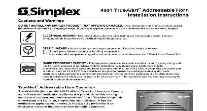
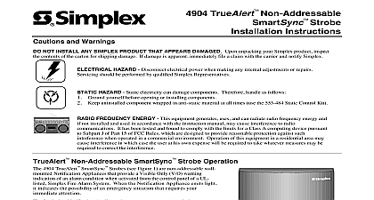
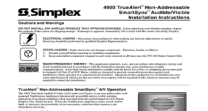
4901 TrueAlert Non Addressable Horn instructions and Warnings NOT INSTALL ANY SIMPLEX PRODUCT THAT APPEARS DAMAGED Upon unpacking your Simplex product inspect contents of the carton for shipping damage If damage is apparent immediately file a claim with the carrier and notify Simplex HAZARD Disconnect electrical power when making any internal adjustments or repairs should be performed by qualified Simplex Representatives HAZARD Static electricity can damage components Therefore handle as follows Ground yourself before opening or installing components Keep uninstalled component wrapped in anti static material at all times use the 553 484 Static Control Kit FREQUENCY ENERGY This equipment generates uses and can radiate radio frequency energy and not installed and used in accordance with the instruction manual may cause interference to radio It has been tested and found to comply with the limits for a Class A computing device pursuant Subpart J of Part 15 of FCC Rules which are designed to provide reasonable protection against such when operated in a commercial environment Operation of this equipment in a residential area may interference in which case the user at his own expense will be required to take whatever measures may be to correct the interference Non Addressable Horn Operation 4901 9820 TrueAlert Horn see Figure 1 is a non addressable wall Notification Appliance that provides an audible warning indication an alarm condition when activated from the control panel of a UL listed Fire Alarm System When the Notification Appliance emits it indicates the possibility of an emergency situation that requires immediate attention Horn is a Notification Appliance that operates on a reverse polarity Appliance Circuit NAC When this NAC circuit is in the polarity or supervision state the Horn does not operate and presents impedance to the circuit The Horn operates when the NAC changes entering the state the Horn powers up it checks the setting of Switch SW1 to whether to operate in either Free Run SW1 or SW1 Mode If the switch is set for Free Run mode the sounds for as long as power is applied Otherwise the Horn waits in for commands from the NAC When switch SW1 is in the SmartSync mode the horn not operate unless connected to a SmartSync Control 4905 9938 4010 Fire Alarm Control Panel or IDNet NAC Extender The factory default setting SW1 is 1 TrueAlert Horn set for SmartSync Mode the Horn responds to Turn ON Turn OFF March Time and Temporal command signals received from the circuit The Horn responds immediately on any valid received command resetting sounder operation to the new mode The will output an audible second pulse every 1.0 second when either March Time or Temporal command is detected with every fourth removed under the Temporal Code 3 command Table 1 for sound output levels and current draw information on the TrueAlert Horn Simplex Time Recorder Co Westminster MA 01441 0001 USA specifications and other information shown were current as of publication and are subject to change without notice and SmartSync are trademarks of Simplex Time Recorder Company C Non Addressable Horn Wiring Make sure that all power is disconnected before starting the installation Connect wiring to terminals as shown Do not loop wires under terminals Break wire runs to provide supervision of Do not bring conduit through the rear of the electrical box Strip lead insulation to 3 8 maximum At the enclosure box connect the contractor wires to the NAC and NAC terminals at the rear of the Horn unit See Figure 2 When connecting more than one Horn to a circuit ensure that correct polarity is maintained for each unit When connecting the last Horn on a circuit connect an end of line resistor EOLR to the Horn terminals ID LABEL TERMINAL TERMINAL TERMINALS ACCEPT WIRES 12 18 AWG VDC POWER INPUT NOTE 4 Horn Rear View VDC FROM APPLIANCE OR PRECEEDING NOTES LAST APPLIANCE CIRCUIT EOLR NOTES HORN NAC HORN NAC HORN Notification Appliances are rated per individual nameplate label Maintain correct polarity on terminal connections Do not loop wires under terminals Refer to the Field Wiring Diagrams supplied with the FACP for detailed NAC wiring information These appliances were only tested to the operating voltage limits of 16VDC and 33VDC Do not these appliances outside these limits doing so may cause appliance to fail to operate and or permanent damage to this equipment 2 TrueAlert Horn Wiring the TrueAlert Non Addressable Horn Figure 3 for mounting the TrueAlert Horn to the enclosure box When surface mounting of the horn the 4905 9937 or 4905 9940 Mount Skirt is recommended Refer to the 4905 TrueAlert NAC Surface Mount Skirt Installation Instructions 574 790 for mounting application Do not bring conduit through the rear of the electrical box mounting screws snugly do not overtighten semi flush mounting install the box either flush with the wall or with a maximum 0.25 inch recess FIT INTO ON THE OF THE COVER GROUP QTY 2 SCREWS CORNER SQUARE BOX FROM 748 472 NOTES 1 AND 2 SUPPLIED COVER SW1 RECESSED IN HOUSING FREE RUN MODE SHOWN SmartSync MODE NOTE 3 HOLES NOTE 2 SQUARE HOLES NOTE 2 and NAC TEST NOTE 3 SQUARE HOLES NOTES 1 AND 2 HOLES OF UNIT NOTE 4 HOLES NOTES 1 AND 2 TrueAlert Horn attaches directly to standard single gang double gang or 4 inch square electrical box s not supplied mounted or surface to the wall surface are two holes for single gang and four holes for double gang electrical box mounting secure the housing to the single gang or box using two mounting screws 6 32 x 1 1 8 inch long not supplied The two mounting screws are placed cross corner top and bottom holes on the double gang installation Mounting the Horn to the 4 inch square electrical box is shown SW1 and NAC and test points are accessible after mounting with the Horn cover removed remove cover press snap release in with a flat tip screwdriver while pulling up cover with other hand 3 TrueAlert Horn Mounting 1 TrueAlert Horn Sound Pressure Level Measurements PRESSURE MEASUREMENT dBA MODE NOTE 1 ANECHOIC ROOM AT TEN SEE NOTE 2 ROOM TEN FEET PER UL464 NOTE 3 coded category covers both Temporal and March Time cadences Average anechoic dBA measurements are measured on axis in a non reflective test chamber using fast meter response Reverberant dBA measurements are a minimum UL rating based on sound power level measurements made in UL reverberant test chamber Safety and Placement of Notification Appliances Appliances and the Fire Alarm System itself have certain limitations and requirements for safety placement installation and Since you must know the limitations and adhere to the requirements keep these instructions at a central location for future reference so all people who use maintain and test the Fire Alarm System have access to this information Appliances do not sense any hazardous conditions such as smoke fire explosion etc they are activated by a control panel part of a system that does sense such conditions Appliances do not provide their own power They receive their power from