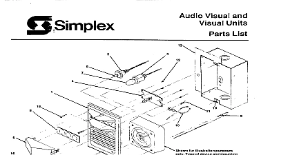
Simplex 4903 4904 Audible Visible Plates

File Preview
Click below to download for free
Click below to download for free
File Data
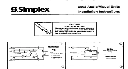
| Name | simplex-4903-4904-audible-visible-plates-9852713064.pdf |
|---|---|
| Type | |
| Size | 1.04 MB |
| Downloads |
Text Preview
OaSimplex Audible Visible Visible Units Lens if Required FLASHER UNITS ONLY Attach the reflector A to the Flasher Printed Circuit PC Board B by lining DO NOT TOUCH FLASH TUBE WITH YOUR with the flash tube D and then pushing the reflector cut out behind See Figure 1 Make sure that the reflector cut out board component surface end and the reflector slot lines up with the flash towards Insert the Flasher PC Board with reflector the lens E by placing the PC Board behind the lens two bottom tabs F and then snapping the Board onto the top tab G See Figure 1 Make sure that the reflector is wrinkle free and behind the flash tube TO STEP 3 ON PAGE 4 OF LIGHT IN PERCENT LENS VIEWING ANGLES Flasher Units 4904 9104 and 4904 9106 or Wall Mount at 24VDC All Other Flasher Listed in Flasher Chart on page 2 4903 Audible Visible 4904 Visible Flasher Units 4905 9901 49059902 Not for use with 4904 9104 Lens Clear with Clear Lens and 9106 Flasher Units ASSEMBLY FLASHER UNITS ONLY 992 smplex Tim Rec co Gardner MA 0144 0001 U S A specil catm an 3 other i Show were c as 0 pubhcahon and am subject 10 change Wltho nOw 574 657 RATING CHART EFFECTIVE RATE CANDELA 24VDC CANDELA 12OV 60Hz POVAC PER ULI 1638 STANDARD Procedure PER SECOND PER SECOND Lens if Required INCANDESCENT UNITS ONLY Attach the reflector A to the Lamp Printed Circuit PC Board B by lining up reflector cut outs C with the lamps D and then pushing the reflector the lamps See Figure 2 Make sure that the reflector towards lamp board surface Insert Lamp PC Board with reflector the lens E by placing PC Board behind the lens two bottom tabs F and then snapping Board onto the top tab G See Figure 2 Make sure that the reflector is wrinkle free and over the lamps RATING CHART ID EFFECTIVE INTENSITY CANDELA 24VDC CANDELA 19.6VDC CANDELA 12OV 60Hz 1 PER ULI 1638 STANDARD OF LIGHT IN PERCENT LENS VIEWING ANGLES FOR PAODUCT THE INCANDESCENT RATING CHART PAGE 2 4903 AudibleAMble 4904 Visible 4905 9904 4905 9905 Not for use with 4904 9104 Lens White with White Lens and 9106 Flasher Units ASSEMBLY INCANDESCENT UNITS ONLY 2 Lens Assembly Audible Visible Visible Only Base 4903 AN only The 4904 9104 4904 9105 and 4904 9106 Flasher Units require a Base Attach the lens assembly to the audible visible base H by placing the four from the Flasher or Lamp PC Board into the wiring channel J and snapping place See Figure 3 lens assembly Visible only The 4904 9104 4904 9105 and 4904 9106 Flasher Units require a Base Attach the lens assembly the visible only base K by placing the four from the Flasher or Lamp PC Board through the base cut out L and snapping place See Figure 4 lens assembly To remove the lens assembly push a small screwdriver lens notches and pull lens assembly away from base See Figure 3 LENS ASSEMBLY TO 4903 AUDIBLE VISIBLE 3 LENS ASSEMBLY TO 4904 VISIBLE ONLY 4 Audible Visible Visible Only Assembly Electrical Back BOX For flasher units only connect wires as shown in Figure 5,6,7,6,9 or 11 incandescent units only connect wires as shown in Figure 12,13 or 14 for or non coded systems BELL CHIME ETC ELK DC WIRE NUTS ARE NOT SUPPLIED NOTIFICATION AND TAPE UNUSED LEADS 5 RATED PER INDIVIDUAL NAMEPLATE DIAGRAM FOR 4903 9101 4904 9101 9103 WITH NOTIFICATION APPLIANCE 21 28VDC LOUT WIRE NUTS ARE NOT SUPPLIED NOTlFlCATlON USE TWISTED SHIELDED AND TAPE UNUSED LEADS FOR ALL MAPNET OR AUDIO WIRING RUN WlTH FLASHER WIRING FOR SYSTEM WIRING SPECIFICATIONS 900 036 FOR 2120 CONTROLS AND 900 0S2 FOR CONTROLS RATED PER INDIVIDUAL NAMEPLATE 6 DIAGRAM FOR 4903 9101 9103 WITH SPEAKER 4904 9101 21 28VDC BELL CHIME ETC WIRE NUTS ARE NOT SUPPLIED NOTlFlCATlON USE TWISTED SHIELDED AND TAPE UNUSED LEADS FOR ALL MAPNET OR AUDIO WIRING RUN WlTH FLASHER WIRING FOR SYSTEM WIRING SPECIRCATIONS 9OD 036 FOR 2129 CONTROLS 900 082 FOR CONTROLS 7 RATED PER INDIVIDUAL NAMEPLATE DIAGRAM FOR 4903 9151 9153 OR 4904 9151 SPEAKER NOTIFICATION 12OV BELL CHIME ETC WlRE NUTS ARE NOT SUPPLIED NOTlFlCATlON AND TAPE UNUSED LEADS RATED PER INDIVIDUAL NAMEPLATE 8 OR 4904 9101 9103 WITH NOTIFICATION APPLIANCE DIAGRAM FOR 4903 9101 21 28VDC WIRE NUTS ARE NOT SUPPLIED NOTIFICATION AND TAPE UNUSED LEADS OR AUDIO WIRING RUN WlTH FLASHER WIRING FOR SYSTEM WIRING SPECIFICATIONS SOD 036 FOR 2120 CONTROLS 9OWS2 FOR CONTROLS FOR ALL MAPNET RATED PER INDIVIDUAL NAMEPLATE 9 DIAGRAM FOR 4904 9104 OR 9106 WITH 4903 9501 BASE AND 2 28VDC ouT RED SELL CHIME ETC WIRE NUTS ARE NOT SUPPLIED NOTIFICATION AND TAPE UNUSED LEADS RATED PER INDIVIDUAL NAMEPLATE 10 DIAGRAM FOR 4904 9104 OR 9106 WITH 4903 9501 BASE AND NOTIFICATION 21 28VDC WIRE NUTS ARE NOT SUPPLIED AND TAPE UNUSED LEADS 11 DIAGRAM FOR 4904 9104 OR 9106 WITH 4904 9501 BASE 2 28VDC WIRE NUTS ARE NOT SUPPLIED NOTIFICATION AND TAPE UNUSED LEADS CIRCUIT PER INDIVIDUAL NAMEPLATE 12 DIAGRAM FOR 4903 9001 OR 9003 WITH NOTIFICATION APPLIANCE VRMS WIRE NUTS ARE