Simplex 4903 Horn-Visible Units - Installation Instructions

File Preview
Click below to download for free
Click below to download for free
File Data
| Name | simplex-4903-horn-visible-units-installation-instructions-3820946157.pdf |
|---|---|
| Type | |
| Size | 1.09 MB |
| Downloads |
Text Preview
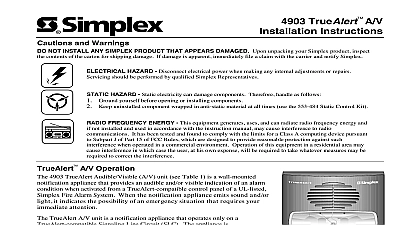
4903 Horn Visible Units Instructions and Warnings NOT INSTALL ANY SIMPLEX PRODUCT THAT APPEARS DAMAGED Upon unpacking your Simplex product inspect the contents of the for shipping damage If damage is apparent immediately file a claim with the carrier and notify Simplex HAZARD Disconnect electrical power when making any internal adjustments or repairs Servicing should be by qualified Simplex Representatives HAZARD Static electricity can damage components Therefore handle as follows Ground yourself before opening or installing components Keep uninstalled component wrapped in anti static material at all times use the 553 484 Static Control Kit 4903 Horn Visible Units are Notification Appliances listed by Underwriters Laboratories UL Notification Appliances provide an audible and or visible indication of an alarm condition when activated from the control panel of a UL listed Simplex Protective Signaling System When Notification emit sound and or flash a light they indicate the possibility of an emergency situation that requires your immediate attention Horn Visible Units have a switch to select Free Run or Synchronous operation of the strobe appliance Selecting Free Run has the strobe flash at a rate determined by a timer circuit in the strobe Selecting Synchronous operation forces the strobe to flash whenever the NAC voltage to zero Safety and Placement of Notification Appliances appliances and the fire alarm system itself have certain limitations and requirements for safety placement installation and test Since you must the limitations and adhere to the requirements keep these instructions at a central location for future reference so that all people who use maintain and the fire alarm system have access to this information appliances do not sense any hazardous conditions such as smoke fire explosion etc they are activated by a control panel as part of a system does sense such conditions appliances do not provide their own power They receive their power from the fire alarm system If power is not supplied to the notification for whatever reason the notification appliances will not provide an audible visible warning THEREFORE BACK UP POWER SUPPLIES OR BACK UP POWER SOURCES ARE REQUIRED FOR THE FIRE ALARM SYSTEM appliances provide a specific rated output level of sound or light The output level must meet the requirements of the intended protected Although the 4903 notification appliances meet the current UL standards for sound output and light intensity the protected area s may have walls carpeting furniture insulation or other obstacles that reduce or even block the sound and or light For all applications the sound and light output must enough intensity to alert all occupants of the protected area s including those occupants that are sleeping or hearing impaired for whatever reason If occupants cannot hear and or see the effect of the notification appliances within the protected area s you must increase the intensity of the sound light or add additional notification appliances so that the occupants can hear an or see the effect of the notification appliances when activated Refer to Fire Protection Association NFPA National Fire Alarm Code 72 Chapter 4 appliances are not a substitute for insurance coverage All users should have adequate levels of life and property insurance install maintain and test notification appliances within their specifications Failure to follow all safety precautions and instructions may result in of life and property due to non functioning notification appliances notification appliances use high voltage To avoid electrical hazards and avoid damage to appliances make sure that the electrical power for the Appliance Circuit is disconnected at the control panel before installing repairing or internally adjusting any notification appliances with electrical power removed some notification appliances such as visible strobes store a high voltage charge The high voltage can cause injury in death from electrical shock DO NOT TOUCH EXPOSED CIRCUITRY placement of notification appliances must conform to appliances are not intended for installation within hazardous locations as defined by the National Electrical Code NEC or the NFPA Contact for information on explosion proof notification appliances designed for hazardous environments candela rating of each strobe unit is marked on the reflector for easy visual identification NFPA standards and guidelines Refer to National Fire Alarm Code 72 Chapter 4 Sound Pressure Level and or Light Intensity Analysis of Intended Protected Areas Authority Having Jurisdiction AHJ Requirements 2000 Simplex Time Recorder Co Westminster MA 01441 0001 USA specifications and other information shown were current as of publication and are subject to change without notice B 1 1 Hz 4903 Horn Visible Units 60 70 Flashes Per Minute Free Running Rating Chart ID MODEL CD MARKING VERT HORIZ X X X X X X X X X Appliance Ratings dBa for 16 V input at 13 mA dBa for 33 V input at 16 ma Available for humid applications Sync flash requires STR series 4010 panel 4009 9201 4009 9301 4009 9807 or use of 4905 9938 4905 9914 4905 9922 sync units to Table 2 for 4903 strobe current rating information 2 4903 Horn Visible Units Strobe Current Rating Chart INPUT VDC mA mA Avg mA Horn ratings are UL measurements Sound power level measurements were made in UL reverberant test chamber at a of 10 feet Mode Switch 1 4903 Horn Visible Units Mode Switch SW1 Location the Horn Visible the enclosure box connect the contractor horn audible wires and the wires for the visible portion to the terminals at the rear of the unit Refer to Figures 2 4 Make sure that all electrical power is disconnected before starting the installation Connect wiring to terminals as shown Break wire runs to provide supervision of connections Do not bring conduit through the rear of the box Strip lead insulation to 3 8 maximum connecting more than one Horn Visible unit to a circuit ensure that correct polarity is maintained on both audible and visible wiring Refer to Figures and 4 When connecting the last Horn Visible unit on a circuit connect the E O L resistor to the terminal block as shown in Figure 2 and 4 For ease of or expanding the circuit mark the last unit location so that the E O L resistor can be easily found Maximum 35 strobe appliances per circuit when synchronous operation is selected Maximum 30 ohms wire resistance between strobe appliances to Field Wiring Drawings of the driving Fire Alarm Control Panel for further instructions appliances were only tested to the operating voltage limits of 16 V to 33 V Do not operate these appliances outside these limits doing so may appliance to fail to operate as intended and or cause permanent damage to this equipment When wiring Horn Visible Units using separate horn and visible notification circuits Figure 3 make certain that you remove cut jumper R12 and R13 shown in Figure 3 Continued 24VDC NON CODED ON AP PLIANCE OR PRECE DI NG ANCE VIS IBLE CI RCUI T TION NE XT NOTIFI CATION LIANCE OR IF LAS T LIA