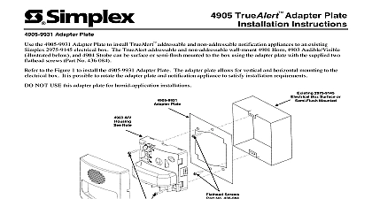
Simplex 4905 TrueAlert Isolator Module Installation Instructions

File Preview
Click below to download for free
Click below to download for free
File Data
| Name | simplex-4905-truealert-isolator-module-installation-instructions-2531486079.pdf |
|---|---|
| Type | |
| Size | 1.09 MB |
| Downloads |
Text Preview
4905 TrueAlert Isolator Module instructions and Warnings NOT INSTALL ANY SIMPLEX PRODUCT THAT APPEARS DAMAGED Upon unpacking your Simplex product inspect contents of the carton for shipping damage If damage is apparent immediately file a claim with the carrier and notify Simplex HAZARD Disconnect electrical power when making any internal adjustments or repairs should be performed by qualified Simplex Representatives HAZARD Static electricity can damage components Therefore handle as follows Ground yourself before opening or installing components Keep uninstalled component wrapped in anti static material at all times use the 553 484 Static Control Kit FREQUENCY ENERGY This equipment generates uses and can radiate radio frequency energy and not installed and used in accordance with the instruction manual may cause interference to radio It has been tested and found to comply with the limits for a Class A computing device pursuant Subpart J of Part 15 of FCC Rules which are designed to provide reasonable protection against such when operated in a commercial environment Operation of this equipment in a residential area may interference in which case the user at his own expense will be required to take whatever measures may be to correct the interference Isolator Module Operation TrueAlert family of Notification Appliances and interface devices provide addressable control and supervision of appliances and circuit wiring Appliances may be operated over a single two wire notification appliance circuit allows T tapping Class B only The TrueAlert Isolator Module provides a means of containing the effects of a short on the TrueAlert Comm Channel and acts as an aid in locating short circuits and circuit fault connections to earth The TrueAlert Comm Channel can be broken into segments in both Class B and Class A circuit topologies Isolator Modules operate relay switches under the control of commands received over the 2 wire TrueAlert from the 4009 TrueAlert Addressable Controller and open those relay switches automatically when a short is detected Isolator Module has an LED that the connected TrueAlert Addressable Controller can drive ON OFF or blink poll Wiring Terminal 2 1 TRUEALERT ISOLATOR INSTR 574 769 REV CONTACTS AMP 30 VDC mA MAX 24 VDC Time Recorder Co MA 01441 Switch 1 TrueAlert Isolator Module Simplex Time Recorder Co Westminster MA 01441 0001 USA specifications and other information shown were current as of publication and are subject to change without notice is a trademark of Simplex Time Recorder Company A Isolator Wiring Make sure that all power is disconnected before starting the installation Connect wiring to terminals as shown Do not loop wires under terminals Break wire runs to provide supervision of Do not bring conduit through the rear of the electrical box Strip lead insulation to 3 8 maximum At the electrical box connect the contractor wires to the PORT 1 PORT 2 and terminals of the Isolator Module See Figure 2 Ensure that correct polarity is maintained across the ports Isolator B Wiring Isolator A Wiring TrueAlert Isolator Module 1 2 ACCEPT WIRES 12 18 AWG NOTE 5 Isolator Module Isolator Module Isolator Module 2 1 1 2 CLASS A CLASS A CLASS A Refer to the field wiring diagrams supplied with the TrueAlert Addressable Controller for detailed circuit wiring information No more than 6 Isolator can be connected at any port Notification Appliances are rated per individual nameplate label Maintain correct polarity on terminal connections Do not loop wires under terminals All circuit wiring connections are supervised and power limited The TrueAlert Isolator Module can only be operated through TrueAlert Addressable Controller or TrueAlert compatible FACP The Isolator Module counts for 3 unit loads on the TrueAlert Comm Channel De rate alarm load line voltage drop allowance by 0.1 V amp of alarm the Isolator Module from an appliance power source less than 17.6 VDC or greater than 32 VDC may cause permanent damage to the module per Isolator Module T tapping is not allowed for Class A wiring For Class B wiring T tapping is allowed Refer to the field wiring diagram for maximum T tapping length 2 TrueAlert Isolator Wiring the TrueAlert Isolator Module TrueAlert Isolator module mounts to the 4 inch square grounded metal electrical box via 2 screws Box depth is on the number and size of conductors used in a particular application the range extends from a minimum 2 1 8 box to a 1 1 2 deep box with a minimum 1 1 2 extension ring Do not bring conduit through the rear of the electrical box Tighten mounting screws snugly do not overtighten For semi flush mounting install the box either flush with the wall or with a maximum 1 4 inch recess Metal Electrical Box box 4 square 102 mm 4 Inch Square 102mm 1 8 54 mm minimum depth 1 8 Inch 54mm Minimum Depth 232 or equal by others 232 or equal by others TrueAlert Isolator Module Square Metal Cover Plate 752 or equal by others 4 Square cover plate 752 or equal by others A cover plate not supplied is required to complete installation 3 TrueAlert Isolator Mounting Isolator Module uses terminals to connect to each wire point Each accepts 2 wires of gauges 12 thru 18 AWG The screws at TB1 accommodate both slotted and Philips drive to the Field Wiring Diagrams for detailed information on maximum wire run distances the Isolator Module Address TrueAlert notification appliance and accessory device has a unique address Each device address is set via an DIP switch as shown in Table 2 See Figure 1 for the general DIP switch location DIP switch position 1 the least significant bit LSB and position 8 is the most significant bit MSB DIP Switches 1 through 6 are used to set the possible 63 address codes DIP Switches 7 and 8 are not used and set to a small screwdriver or pen to set the switches and then write the address on the re sealable label This information an aid in troubleshooting the system The TrueAlert Comm Channel 4009 TrueAlert Addressable NAC Controller or TrueAlert compatible FACP only address codes 1 through 63 DIP switch in 1 position is ON while DIP switch in 0 position is OFF 1 TrueAlert Isolator Module DIP Switch Address Chart SHOWN IS AT ADDRESS 7 ON OFF USED TO OFF FOR USE SWITCHES 5 AND 6 THRU 4 A