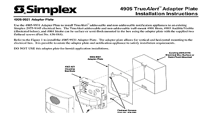
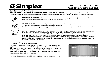
Simplex 4905 TrueAlertQuickAlert Skirt Installation Instructions

File Preview
Click below to download for free
Click below to download for free
File Data
| Name | simplex-4905-truealertquickalert-skirt-installation-instructions-5043829761.pdf |
|---|---|
| Type | |
| Size | 1.13 MB |
| Downloads |
Text Preview
4905 TrueAlert Installation Instructions the 4905 red and white Skirts to install TrueAlert addressable and non addressable notification appliances in surface mounted applications to conceal the box not supplied 4905 9937 Red and 4905 9940 White Skirts TrueAlert addressable and non addressable wall mounted 4901 Horn 4903 Audible Visible illustrated below and 4904 Strobe are installed using the skirt two 8 panhead screws supplied with appliance which mount to a 4 inch square electrical box box depth 1 1 2 inches The single gang and double gang box box depth 1 1 2 inches require 6 panhead screws not supplied for skirt installation Single Gang A V Strobe Double Gang A V Strobe Double Gang Horn Single Gang Horn Red Skirt or White Skirt 4 Inch Square Horn A V Strobe Mount Applications Only Mounted Electrical Box 1 2 Inches Deep Maximum Hole Mounting Legend Square Shown C D D D A V Note 1 Note 4 Note 3 Screw Holes for Box Mounting Not Supplied Notes 1 and 2 Panhead Screws from Ship Group Qty 2 for 4 Square Box mounting only Screw Holes for Single Electrical Box Mounting Not Supplied Notes 1 and 2 Screw Holes for 4 Inch Box Mounting Notes 1 Cover Note 5 TrueAlert Horn A V and Strobe appliances are installed using two panhead screws For 4 inch square electrical box installation use the supplied 8 panhead ship group 748 472 The screws mount cross corner through the housing and skirt holes and secure to the electrical box Single and double gang box installations require 6 panhead screws not supplied Use the appropriate mounting holes for electrical box configuration Refer to appliance installation instructions for box and interconnection requirements TrueAlert Non Addressable Horn Installation Instructions 574 720 TrueAlert Non Addressable Audible Visible Installation Instructions 574 721 TrueAlert Non Addressable Strobe Installation Instructions 574 722 TrueAlert Horn Installation Instructions 574 764 TrueAlert Audible Visible Installation Instructions 574 768 TrueAlert Strobe Installation Instructions 574 767 notification appliance housing has four cutout slots that attach to the four skirt tabs for ease of installation when mounting the housing skirt to the box Conduit knockouts are provided on all four sides of the skirt remove cover press snap release in one at a time with a flat tip screwdriver while pulling up cover with other hand 2000 Simplex Time Recorder Co Westminster MA 01441 0001 USA specifications and other information shown were current as of publication and are subject to change without notice is a trademark of Simplex Time Recorder Company C 4905 9941 Red 4905 9942 White Speaker and 4905 9946 Red 4905 9947 White Speaker Visible Skirts TrueAlert wall mount 4902 Speaker and 4903 Speaker Visible appliances are installed using the skirt and two 8 panhead screws supplied which mount to 4 inch square electrical box with extension ring box depth is 3 inches Red Skirt or White Skirt Mount Applications Only Square Mounting Holes Inches Deep Maximum Inches Deep Mounted Square Electrical Box 1 Inch Extension Ring Speaker Housing Note 1 Square Mounting Holes Speaker Cover Note 5 Square Mounting Holes Panhead Screws from Ship Group Qty 2 Note 3 Red Skirt or White Skirt Mount Applications Only Surface Mounted Square Electrical Box Inches Deep 1 Inch Extension Ring Inches Deep Maximum 4 4 S V Note 1 Square Mounting Holes Wall Mount S V Cover Note 5 Note 3 Panhead Screws from Ship Group Qty 2 TrueAlert Speaker and S V appliances are installed using two panhead screws For 4 inch square electrical box installation use the supplied 8 panhead ship group 748 472 The screws mount cross corner through the housing and skirt holes and secure to the electrical box Refer to appliance installation instructions for box and interconnection requirements TrueAlert Speaker Installation Instructions 574 765 TrueAlert Speaker Visible Installation Instructions 574 766 notification appliance housing has four cutout slots that attach to the four skirt tabs for ease of installation when mounting the housing skirt to the box Conduit knockouts are provided on all four sides of the skirt remove cover press snap release in one at a time with a flat tip screwdriver while pulling up cover with other hand C


