Simplex 5100 and 5120 Series Wiring Connection Options & Accessories

File Preview
Click below to download for free
Click below to download for free
File Data
| Name | simplex-5100-and-5120-series-wiring-connection-options-accessories-1298503476.pdf |
|---|---|
| Type | |
| Size | 1.09 MB |
| Downloads |
Text Preview
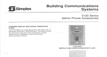
Communications Systems and 5120 Series Connection Options and Accessories Terminal Cabinet this cabinet when punch blocks or screw terminal cannot be mounted in the equipment rack Weld are provided for mounting the 5120 9924 back see page 4 for dimensions A cover plate is to protect wiring and blocks See Figure 1 Terminal Block Back Board back board provides space for mounting a maximum eight 8 5120 9920 punch down or 5120 9923 screw blocks Pre drilled holes provide a convenient arrangement for the blocks See Figure 1 Double Connector Punch Block this block for field wiring of devices with 24 AWG to AWG wires Two 25 pair male connectors are to connect 48 points to the 5100 Series Main Use punchdown tool 553 644 See Figure 1 Single Connector Punch Block this punch block for field wiring of devices with AWG to 20 AWG wires One 25 pair male connector provided on the left side of the block to connect points the 5100 Series Main Console Bridge clips are used to circuits Use punchdown tool 553 644 See 2 Screw Terminal Block this screw terminal block for field wiring of devices 18 AWG and larger twisted pairs One 25 pair male is provided for interconnection to the 5100 Main Console See Figure 3 and 5120 9931 Interconnection are two sizes of 25 pair interconnection cables the 5 ft 1.5 m long for use with wall cabinets or terminal blocks are mounted within the equipment and the 5120 9931 15 ft 4.6 m long for use with cabinets when terminal blocks are not mounted the equipment rack Use 5120 9931 cables for the wall rack 5100 9865 and 5100 9867 Each is provided with a 25 pair female connector on each Please Note These items are included in the Installation See data sheet S5120 0012 for additional information 1 5120 9911 Terminal Cabinet with Terminal Block Back Board Double Connector Punch Blocks 8 2 5100 9920 Single Punch Block 3 5120 9923 Terminal Block 3 2010 Punch Block punch block not shown is used when or DK S30A suppression modules are on wiring leaving or entering the building wire runs are terminated to one side of the block suppression modules to bridge connections to the wiring side A DK IBNC28 Punch Block Ground is required for each 5120 9928 Punch Block For ground protection per the National Electrical Code the DK IBNC28 to an approved ground with 12 AWG Use punchdown tool 553 644 Standoff Bracket brackets not shown help to provide efficient installations They allow cables to be run the punch block providing a closed and protected channel Station Line Suppressor Module DK S30A Station Line Suppressor Module provides protection for the station and circuits Up to four modules may be required for 5110 5115 or 5120 station circuits as well as 5195 digital station When used on the 5120 9920 the suppressor the punch block station capacity by 50 Use the punch block when mounting suppressors where wiring exits or enters a building not The suppressor module cannot be used with the screw terminal punch block See Figure 4 Admin Port SLT Suppressor DK DTKSL95A Admin Port Suppressor Module transient protection for 5105 5110 5115 or Series admin ports loop start trunks as well as for SLT ports See Figure 4 Punch Block Ground Bar punch block is used when suppression modules are to the 5120 9920 Punch Block For ground per the National Electrical Code tie the to an approved ground with 12 AWG wire Figure 4 Admin Port Suppressor Module Terminal Connector 5120 9909 Terminal Connector accepts the Admin Port Suppressor Module which makes a stand alone surge suppressor for two admin ports provides screw terminal connections See Figures 5 6 Station Line Admin suppressor appearance ratings Block Bar 4 5100 9920 Punch Block with DK IBNC28 Block Ground Bar and Suppressor as noted 5 Admin Suppressor 6 3 2010 Impedance Matching Module 5120 9926 Impedance Matching Module is used to the audio signal from the 5100 Series System station output to drive speakers or a booster amplifier It mounts on the station speaker pins of a 5120 9920 punch Two screw terminals and an RCA female jack are for connecting to the inputs of amplified or a booster amplifier See Figure 7 below Volume Control Module 5120 9927 Volume Control Module is used to the audio to two 45 Ohm speaker circuits when controls are not present at the speaker location It on a punch block and has four screw terminals for to the 45 Ohm speakers It is intended to be with the 5120 9140 or 5130 9140 station boards Figure 8 below 7 5100 9920 Punch Block with 5120 9926 Matching Module 8 5100 9920 Punch Block with Volume Control Module punchdown tool 553 644 Selection Reference Cabinet see page 1 for details dimensions on page 4 Block Back Board see page 1 Terminal Block see page 1 Connector Punch Block see page 1 Connector Punch Block see page 1 Block requires a DK IBNC28 Punch Block Ground Bar see page 2 ft 1.5 m ft 4.6 m Bracket see page 2 Matching Module see details above Control Module see details above Cables see page 1 Modules with Compatibility Reference see page 2 Line Suppressor Module Admin Port SLT Suppressor Block Ground Bar Port Suppressor Module Connector use for one or two circuits punch block required Application compatible Intercom Admin Circuit Speaker Switch Output Circuit 3 2010 Cabinet Dimensions is a registered trademark of Tyco International Services GmbH and is used under license Simplex and the Simplex logo are trademarks of Tyco International Ltd and its and are used under license 2010 Tyco Safety Products Westminster All rights reserved All specifications and other information shown were current as of document revision date and are subject to change without notice Safety Products Westminster Westminster MA 01441 0001 USA 3 2010