Simplex 636-341UPSChangeout
File Preview
Click below to download for free
Click below to download for free
File Data
| Name | simplex-636-341upschangeout-5623801947.pdf |
|---|---|
| Type | |
| Size | 1005.86 KB |
| Downloads |
Text Preview
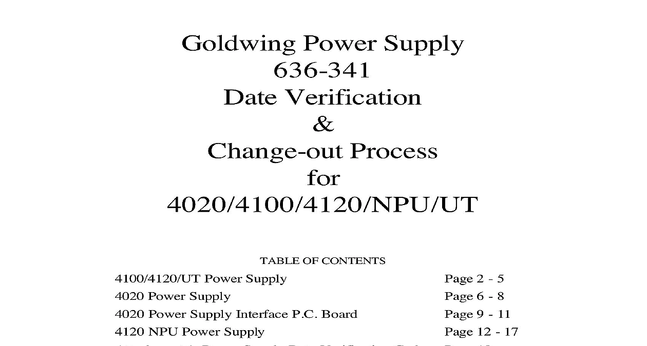
Goldwing Power Supply Verification Process OF CONTENTS Power Supply Power Supply Power Supply Interface P C Board NPU Power Supply 1 Power Supply Date Verification Code 2 PCA Power Supply Marking 2 5 6 8 9 11 12 17 18 19 by of Change History Clark Clark new process bullet to Changed Bullet Date Code to February 1992 to March Changed name of Attachment 1 to Power Date Verification Code Change out doc RMC Rev 2 1 of 19 Goldwing Power Supply Verification and Change out Process task go easier Before starting this process read it through completely and get familiar with the steps to make Remember to follow all Electrical and Static safety practices while performing these process Always power down the system from the Electrical Breaker panel and tag out that breaker to accidental application of power during the time when the unit is being serviced Battery Power Always use Static wrist straps when handling Printed Circuit boards and Electronic assemblies Upgraded Power Supplies that do not require replacement may be identified in the following A small white round label with an located on the right side of the three place terminal TB1 at the top of the power Supply and or located on the left side of the Power Interface Board adjacent to the ribbon cable connector P 9 A yellow strip as shown on Attachment 2 of this document A Serial Tag with a Date Code subsequent to March 1997 See Attachment 1 Tools removal and Date Code verification Process Driver w Assorted bits Flat blade Screwdriver pair of pliers Pick up Tool Flat blade Screwdriver Paint Pen Boise Cascade N263605 Page 730 in 2000 Catalog Open the system door and remove the retainer from the panel Un fasten and lower the Front Panel Display to expose the Goldwing Power Supply Assembly mounted in the upper bay right hand side Unplug the AC power cable Green White and Black harness from the lower connector of Goldwing Power Supply Assembly Unplug the Battery Harness Red and Black harness located in the upper right hand portion of Goldwing Power Supply Assembly Change out doc RMC Rev 2 2 of 19 Goldwing Power Supply Verification and Change out Process Un plug any harnesses that are installed in any of the following connectors P 4 P 5 P 14 P P 17 and lift any field wiring that is landed on TB 2 terminal block Mark and make note of the location of the harnesses and field wiring for ease re installing of them later in this process Remove the four 4 Torx screws from the top and bottom brackets on the Power Supply These four screws are the only fasteners that hold the Power Supply into the apply support to the supply when removing these screws Remove the Power Supply Assembly from the panel Inspect the Serial Tag on the back of the for verification of date code Verification of the Serial number is what is important Using the Power Supply Date verification Code Chart Attachment 1 of this document the Assembly Date of the supply the determined date code is February 1992 through March 1997 then the supply must be for a Replacement Power Supply Continue to the next step of this process the 565 247 Power Supply Interface board the determined date code is later than March 1997 mark the supply with a yellow paint in the appropriate spot as per the Marking sheet Attachment 2 of this Skip to the the Supply section of this process to put the Supply back into the panel the 565 247 Power Supply Interface board from the Goldwing Power Supply the removed Goldwing Power Supply Assembly to a suitable workstation to perform the steps for removing the Power Supply Interface board and then re installing it back onto a Power Supply Assembly Carefully unplug the ribbon cable from P 9 connector on the Interface board On earlier built units there may be a black locking tab that holds the ribbon cable in In this case carefully lift this tab and remove the ribbon cable Unplug the two harnesses labeled from the P 11 and P 12 connectors These are next to the two Gold resistors in the upper right hand corner of the assembly Using the Medium Flat blade screwdriver loosen the three screws on the top mounted terminal and remove the Yellow CHG Red and Black wires Change out doc RMC Rev 2 3 of 19 Goldwing Power Supply Verification and Change out Process Using the Torx driver T 15 bit remove the two screws and lockwashers fastening down the board to the Supply assembly Screw locations are marked and To remove the Interface board from the Supply Assembly use the pliers and squeeze together the tops of the four 4 plastic stand offs and at the same time lift the gently to release it from the Supply Assembly when removing the board watch carefully for the two loose spacer stand offs that are with the Torx screws for fastening the board to the assembly the 565 247 Power Supply Interface board onto the Goldwing Power Supply Insert four 4 snap stand offs spares included in the Hardware Envelope into the Power Supply Position the Interface board onto the Power Supply assembly the four snap stand offs with their respective holes and press the board down gently at stand off at a time using your fingers closely placed near the mounting holes for support Carefully position the two 2 spacer stand offs spares included in the Hardware Envelope the Interface board and the Power Supply assembly in the location where the two screws fasten the board down location marked on PCB as Con2 and Con3 Fasten the board to the Supply using the two Torx screws and lockwashers Insert the ribbon cable into the P 9 connector noting proper pin alignment Install and tighten the three wires Yellow CHG Red and Black to the terminal block the top of the Supply assembly using the Medium Flat blade screwdriver In the upper right hand portion of the board install the two 2 harnesses labeled the P 11 and P 12 connectors The one from the upper Gold resistor goes to P 11 and one from the side mounted Gold resistor goes to P 12 the Power Supply Carefully position the Approved Replacement Power Supply back into the panel and align holes in the mounting bracket with the screw holes and attach the supply using the four 4 screws and lockwashers Plug in the AC and Battery harnesses back into the Power Supply Change out doc RMC Rev 2 4 of 19 Goldwing Power Supply Verification and Change out Process Install any of the harnesses and field wiring back to the proper connection locations as marked from Step 5 of the Removal process Start up Restore AC power to the panel from the Breaker panel and then connect the batteries after the initializes and verify all troubles on the panel If the Supply didn need to be changed out with a Replacement Power Supply then power up panel and simply verify the supply taps output and basic system operation If the Power Supply was changed out then perform required testing as per NFPA Standards 7 1.6.2 All Auxiliary System devices obtaining power from the affected Power taps need to be 100 tested In addition 10 of non affected devices up to a quantity 50 also need to be tested Change out doc RMC Rev 2 5 of 19 Goldwing Power Supply Verification and Change out Process This product requires the replacement of the Power Supply and the Power Supply Interface Before starting this process read through it and get familiar with the steps to make this task go Remember to follow all Electrical and Static safety practices while performing these process