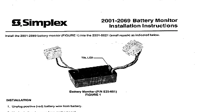
Simplex Battery Monitor Installation Instructions
File Preview
Click below to download for free
Click below to download for free
File Data
| Name | simplex-battery-monitor-installation-instructions-6473820159.pdf |
|---|---|
| Type | |
| Size | 887.95 KB |
| Downloads |
Text Preview
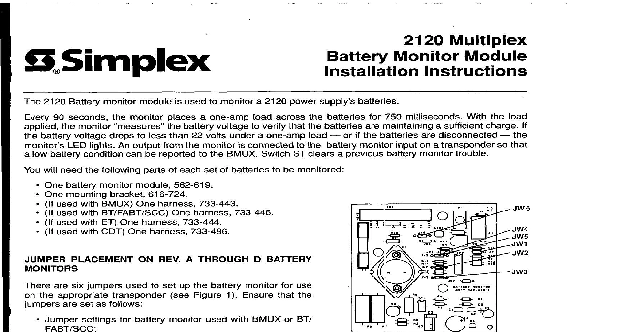
a5implex Multiplex Monitor Module 2120 Battery monitor module used to monitor a 2120 power supply batteries monitor monitor places a one amp battery voltage 90 seconds battery voltage drops to less than 22 volts under a one amp LED lights An output from the monitor low battery condition can be reported connected the BMUX Switch Sl clears a previous battery monitor the battery monitor or if the batteries are disconnected on a transponder across verify that the batteries are maintaining a sufficient charge 750 milliseconds With batteries load that will need the following parts of each set of batteries be monitored 1 A t lrough D Battery Monitor Locations One battery monitor module 562 619 One mounting bracket 616 724 used with BMUX One harness 733 443 used with BT FABT SCC One harness 733 446 used with ET One harness 733 444 used with CDT One harness 733 486 PLACEMENT ON REV A THROUGH D BATTERY are six jumpers used to set up the battery monitor the appropriate Figure 1 Ensure are set as follows use the Jumper settings battery monitor used with BMUX or BT 1 2 JWl JW5 and JW8 OUT JW3 and JW4 IN Jumper settings battery monitor used with ET l 2 JW3 and JW4 OUT JW5 and JW8 IN Group l must all be IN or OUT Group 2 or Group l must all be opposite damage will result SETTINGS ON REV E AND LATER BATTERY switches on DIP switch package S2 set up the battery monitor use on the appropriate Figure 2 Ensure that switches are set as follows Switch settings battery monitor used with BMUX or BT l S2 4 S2 5 and S2 6 CLOSED or ON 2 S2 1 S2 2 and S2 3 OPEN or OFF 1994 Simplex specifications Recorder Co other were current as of publication are subject change without notice 2 E and Later Battery Monitor P Switch Location 575275 Switch settings for battery monitor used with CDT and ET R O U P I S2 4 S2 5 and S2 6 O P E N or OFF R O U P 2 S2 1 S2 2 and S2 3 C L O S E D or O N N Group l switches must all be O P E N or C L O S E D Group 2 switches must all be opposite to Group switches or equipment damage will result N Procedure A if the monitor will be used with a B M U X Procedure B if the monitor will be used with a BT FABT SCC Procedure C if the monitor will be used with an ET Procedure D if the monitor will be used with a CDT R O C E D U R E A N Save all RAM based programs before proceeding Remove power to the B M U X by Disconnecting batteries first Disconnecting A C last Remove the existing 733 206 harness that connects the m otherboard to the power supply and the converter Connect the 733 443 harness to the m otherboard converter power supply battery harness and battery monitor using Figure 3 as a reference E D I 5 V TO C O N V E R T E R B O A R D TBl 8 L K O V TO C O N V E R T E R B O A R D Tel 7 3 3 4 4 3 Harness Showing B attery M o nitor Connections O B A l T E R Y H A R N E S S 3 Do one of the following For 6 unit backboxes Mount the 616 724 bracket the lowest position on the right mounting For 4 unit backboxes Mount the 616 724 bracket the top position on the right mounting Mount the battery monitor module on the lower half of the bracket Activate switch Sl on the monitor clear the trouble by the monitor on power up Restore power to the BMUX by Connecting AC power first Connecting batteries B Remove power to the BT FABT SCC by Disconnecting batteries first Disconnecting AC last Remove plug existing harness connects connectors P3 and P4 on the power supply to the battery harnes Connect 733 446 harness connectors P3 and P4 on the power supply existing harness and batter module using Figure 4 as a reference TO TBl 10 TO TBI 9 TO TBl 8 TO TBI 7 TO TBl 6 TO TBl 3 TO TBl 2 TBl ON MONITOR PLUG P3 PLUG P4 n 4 Harness Showing Battery Monitor Connections Mount the 616 724 bracket the lowest position on the right mounting Mount the battery monitor module on the lower half of the bracket Restore power to the power supply by Connecting AC power first Connecting batteries Activate switch Sl on the monitor momentarily clear the trouble by the monitor C Remove power the ET by Disconnecting Disconnecting AC last Remove existing 733 243 harness connects power supply the battery harness plug Remove 733 371 harness connects power supply the power converter Connect 733 444 harness the power supply power converter and battery monitor using Figure 5 as a TO TBI 10 TO TBI 9 TO TBI 8 TO TBI 7 TO TBI 6 TO TBl 4 TO TBI 3 TO TBI 2 TBI ON MONITOR TBI OF POWER CONVERTER Harness Showing Battery Monitor Connections 5 Mount 616 724 bracket the lowest position on the right mounting Mount battery monitor module the lower half of the bracket Restore power the power supply by Connecting AC power first Connecting batteries Activate switch Sl on the monitor momentarily clear the trouble by the monitor D Remove power the CDT by Disconnecting Disconnecting batteries AC last and Remove existing harness connects power supply the battery harness plug Remove existing harness connects power supply the CDT board Connect 733 486 the power supply CDT board and battery monitor using Figure 6 as a TO TBi IO TO TBI 9 TO TBI 8 TO TBI 7 TO TBl 6 TO TBI 4 TBI ON MONITOR TB7 OF CDT BOARD TO PLUG P4 Harness Showing Battery Monitor Connections 6 Mount the 616 724 bracket the lowest position on the right mounting Mount battery monitor module the lower half of the bracket Restore power the power supply by Connecting Connecting AC power first and batteries Activate Switch Sl on the monitor momentarily clear the trouble by the monitor 575 275