Simplex BMUX Local Printer Maintenance

File Preview
Click below to download for free
Click below to download for free
File Data
| Name | simplex-bmux-local-printer-maintenance-2136857094.pdf |
|---|---|
| Type | |
| Size | 843.85 KB |
| Downloads |
Text Preview
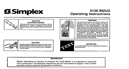
S Simplex Multiplex BMUX Local Printer FIRST and AC power this system system When connecting AC power FIRST and HAZARD power when maklng any adjustments servicing Simplex Representatives be performed by quali repalrs local printer board mounted on the right hand side of the BMUX Access panel and is controlled by the printer door and the front panel of the BMUX The provided obtained by opening you this publication How to replace the local printer paper How to make adjustments which may be required when you replace the printer paper How to the operating voltage for the local printer the local printer print head How to TO REPLACE THE PRINTER PAPER Replacement See Figure 1 Press paper ADVANCE button on front of printer on take paper until printed portion reel Lift latch tab 1 and swing side panel 4 open Tear paper at edge of each roll two places Remove center shaft 2 from take up shaft Remove of paper shaft and Remove roll of paper on supply reel and discard Press paper ADVANCE of paper and discard Place new roll of paper on supply shaft Loosen it will feed to printer rear of printer of paper and ensure PC board assembly Feed end of paper through printer assembly and plate button to pull paper through assembly 2 shows locations Leave 14 16 inches of free for loading paper guide Printer 1 Feed paper through slot at top of paper guide Insert paper 3 into slotted shaft and reassemble 2 to captivate end of paper Remove slack paper by pressing REWIND Test printer by entering a command on keyboard Rotate Close side panel 4 and lock in place by pressing button 1 down 1990 Simplex Tie specifications Co Gardner WO14414QOl other were current as of publication are subjeU change without notice 575 541 6 90 of Paper Alignment Between Printer PC Board Assembly See Figure 2 Loosen 4 fastening screws 1 on rear of PC board Press paper ADVANCE operate With printer operating check to see that paper is on the paper guide on front of unit 3 paper to center paper screw PC board Retighten Adjustments on Printer Take up Assembly Figure 2 Press paper ADVANCE button to operate printer During operation verify that the paper is centered do not drag or roll over and that the paper no excess slack See 5 in illustration To adjust paper tension screw 6 on pivot and top fastening screw 7 of drive motor for proper tension and retighten screws With operating of paper If paper edges are frayed or slightly over above adjustments AND INSTALLING THE PRINTER ASSEMBLY 7 HEAD BOARD ASSEMBLY Printer 2 Replacement of the local printer normally only involves of the print head and PC board See Figure 2 for a pictorial of the local printer assembly remove the local printer REMOVE ALL POWER TO THE BMUX AS FOLLOWS Disconnect batteries first Disconnect AC last Disconnect harness connecting local printer print head assembly to the printer controller board Remove screws securing print head assembly the local printer and remove print head Install the new print head assembly using the screws removed in Step 3 Connect the harness from the printer controller board to the connector on the new print head assembly On the printer controller board adjust R23 fully clockwise Apply power to the BMUX as follows Connect AC first Connect batteries Adjust the local printer operating voltage as described this publication TO ADJUST THE PRINTER OPERATING VOLTAGE are two types of local printers you might see in a 2120 The TI model 616 484 printer which requires an 18V operating voltage The Gulton model 616 877 printer which you will see in all new 2120 installations Gulton model printer is labeled with the required operating voltage no longer used in 2120 systems use a local printer To determine which printer in your system assembly the printer controller board board then you have a TI model printer a pluggable there cable connected at the local printer circuit board part of the print this board other than the one going the the ribbon cable is soldered you have a Gulton model printer will have to adjust the local printer operating voltage only under the following conditions You are replacing local printer with a new unit You are replacing printer controller board 562 095 located either on the underside of the local printer print head label for the new printer operating voltage or on the local printer side panel BE SURE TO CHECK THIS LABEL BEFORE ADJUSTING THE OPERATING VOLTAGE The BMUX printer controller board is located on the rear right corner of the BMUX front panel Locate Cl 5 and R23 on the lower right hand corner of the printer controller board using Fig 3 as a reference Set your VOM to the GODCV scale USING ALLIGATOR CLIPS connect your VOM across Cl5 as shown in Figure 3 DO NOT EXCEED YOUR PRINTER RATED OPERATING VOLTAGE you exceed the operating you will destroy the print head Right Hand Corner of the Controller Board 3 Adjust R23 if necessary until your VOM reads the proper operating voltage for the printer being used THE PRINT HEAD clean the thermal print head as a reference you look at the bottom of the local printer the front of the BMUX front panel you can see the printer print head Periodically you must clean the print head using an uncoated piece of paper such as typing Pull down gently on the print head so that it moves away from the surface of the printer paper Use Figure While holding print head down use an uncoated piece of paper to rub back and forth across the print The print head is easy to clean so RUB GENTLY Release the print head to return it to its normal position the Print Head 4 8 90