Simplex Console and Console Options Installation
File Preview
Click below to download for free
Click below to download for free
File Data
| Name | simplex-console-and-console-options-installation-6327081549.pdf |
|---|---|
| Type | |
| Size | 746.00 KB |
| Downloads |
Text Preview
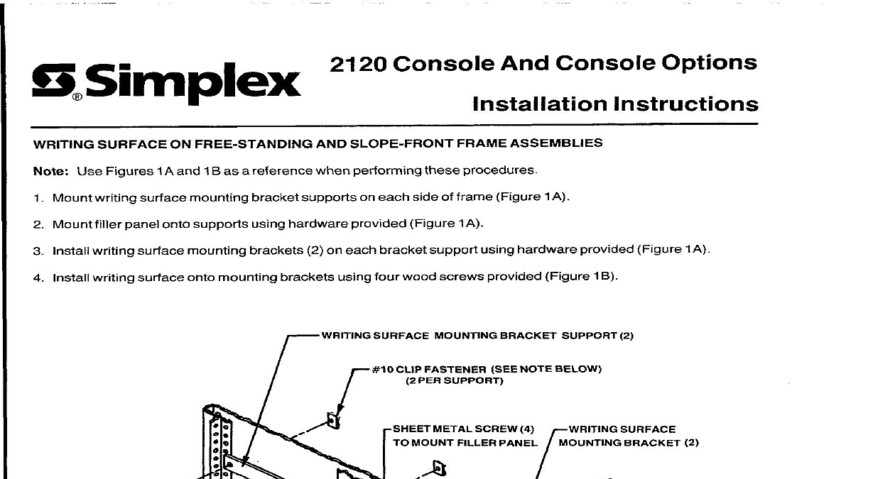
S Simplex 2120 Console And Console Options SURFACE ON FREE STANDING AND SLOPE FRONT FRAME ASSEMBLIES Use Figures 1 A and 1 B as a reference when performing procedures Mount writing surface mounting bracket supports on each side of frame Figure 1 A Mount filler panel onto supports using hardware provided Figure 1A Install writing surface mounting brackets 2 on each bracket support using hardware provided Figure 1A Install writing surface onto mounting brackets using four wood screws provided Figure 1 B WRITING SURFACE MOUNTING BRACKET SUPPORT 2 METAL SCREW 4 r WRITING SURFACE MOUNT FILLER PANEL CLIP FASTENER NOTE BELOW PER SUPPORT BRACKET NOTE BELOW PER SUPPORT PANEL PER BRACKET from frame bottom and screw at 35th mounting 1 A 1987SimplerTimeRecorderCo Mass 01441 0001 USA I PANEL SCREWS PER BRACKET 1 B A WRITING DESK AND DRAWER Use Figure 2 as a reference when performing procedures Attach two levelers to each support leg Install support legs onto desk top aligning mounting holes with inserts Use four machine screws provided There are three sets of inserts where support screw as appropriate to rack and inner insert on opposite side flush mounting mounting screws may be inserted Choose one for each side of frame assemblies choose outer insert on side Install modesty panel between support legs using hardware provided Install drawer guide on underside of desk top using hardware provided on left or right side as desired Insert drawer into drawer guide Mount wiring channel if required on underside of desk top between support legs using wood screws provided CHANNEL IF USED CHANNEL PANEL SCREY SCREW 2 LEG 2 2 PRINTER STAND Assembly of printer stand is similar to assembly of writing desk Desk drawer is not used for printer stand Figure 2 as a reference while performing procedures Attach two levelers to each support leg Jnstall support legs onto desk top aligning mounting holes with inserts Use four machine screws provided Install modesty panel between support legs using hardware provided REQUIREMENTS FOR ELECTRICAL Locate console assembly containing 2120 AC Input and BT I O modules Refer to Figure 3 Using appropriate provide holes in bottom of frame assembly for conduit entry OF RACK 35 INCHES WALL OR DOOR T 6.00 AREA BOTTOM OF 3 5 87