Simplex Fire Alarm Network Reference; Network Communications, Options and Specifications [For INTERNATIONAL USE ONLY];

File Preview
Click below to download for free
Click below to download for free
File Data
| Name | simplex-fire-alarm-network-reference-network-communications-options-and-specifications-for-international-use-only-0584129376.pdf |
|---|---|
| Type | |
| Size | 890.56 KB |
| Downloads |
Text Preview
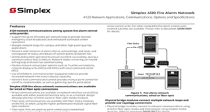
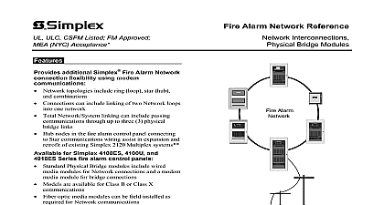
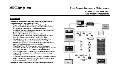
Alarm Network Reference Communications and Specifications Optics Simplex Fire Alarm Network communications available for wired or fiber optic connections Wired communications are available on Network modules available with either wired only or as a modular design allowing of either wired or fiber optic media modules Fiber optic communications are available with fiber modules on the Network interface modules or using the higher performance multiple signal optic modems Fiber optic links are point to point continuous connections between Fire Alarm nodes LED status indicators assist with system setup and communication signal modems use optical transmitters to provide transmission distances compared to copper over 20 miles 32 km may be possible with single mode fiber Designs are optimized for fiber type models are for single mode fiber or multi mode fiber Multiple signal modems are two slot modules and are with separate enclosures if required for Network node control panels modular interface modules provide Class B or Class X communications using wired or fiber optics selectable separately to match requirements media module details Provides isolated earth detection Compatible with Simplex isolated loop and protectors Electrical characteristics are similar to RS 485 signal fiber optic media module Fiber optic links provide immunity to electrical short circuits and ground conditions LED based fiber optic media module uses two fibers to communicate has type ST compatible with 62.5 125 or 50 125 fiber Bi Directional Couplers are available to allow use of fiber cable for Network communications communications fiber optic modules Laser based half duplex communications over single connections Available for single mode or multi mode fiber Refer to information summary on pages 2 and 3 and to sheet S4100 0049 for additional feature Alarm Network Communications Wired or Fiber Optic Continued Bridge Modules connect multiple loops and provide Star topology Physical Bridge Modules connect to Network using wired or fiber optic media and using modem media modules refer to sheet S4100 0057 for details TCP IP Physical Bridge Modules are similar but LAN Local Area Network compatible refer to data sheet S4100 0029 for Panel List nodes include the following Simplex fire products 4100ES 4100U 4007ES 4010ES and 4010 Series Fire Control Panels and 4100ES or 4100U Network Units NDU 4190 Series TrueSite Workstations TSW 4190 Series Network System Integrators Legacy 4120 Series panels NPU and 2500 NDU 4190 IMS and GCC systems 4020 4002 Series and retrofitted 4100 4100 and 2120 systems NOTE Refer to individual product data sheets for specific product listing details see data sheet list on page 3 7 2016 Network Communications Module Selection Reference Interface Modules for Fire Alarm Control Panels and TrueSite Workstation Network Interface for Master Controller Network Interface for Redundant Master Controller Media Module Optic Media Module Interface with fixed wired media PCI slot card Network Interface PCI slot card Media Module Optic Media Module Interface with fixed wired media Network Interface Network Interface Media Module Optic Media Module Interface Card Modular Network Interface Media Card Media Card two media modules below on 4100 6078 or 4100 6061 Interface also used with System Integrator two media modules below on 4190 6061 Network two media modules below on 4010 9817 or 4010 9922 Interface two media modules below on 4007 9810 Network Card Multiple Signal Modems Reference refer to data sheet S4100 0049 for additional information Type Mode Mode Mode Fiber Modem Assembly Fiber Modem Assembly Fiber Modem Assembly for Expansion Mounting direct mounting onto a 4100ES 4100U bay Fiber Modems are required to ordered in pairs Left Port Fiber Modems only to Right Port Fiber Modems if required one maximum Fire Alarm Network Example with Multiple Communication Media to ST Coupler others or 50 125 Multi mode graded single fiber optic cable requires coupler at each end 1 CARD Protection is required when leaves or enters a building 2 CARD communications Network audio can be the same fiber modems single fiber signal modems are modules and fit in bay or in separate if required fiber optic media require dual fiber twisted shielded pair to building Per NFPA 70 NEC shielded wiring is required when wiring leaves the building twisted pair external to requires overall shield N CARD 5 CARD cards are single slot and fit in 4100ES 4100U CPU bay twisted pair or twisted pair dry facility owned 4 CARD 3 CARD 7 2016 Multiple Signal Fiber Modems Network communications or local Control Panel communications Multiple signal fiber communicate a variety of system signal to a single fiber optic cable These modules dual slot module sized and can be housed in external for connection to smaller control panels Please to data sheet S4100 0049 for details is a summary of the distance specifications for the Signal Fiber Modems Multiple Signal Fiber Optic Modem Distance Specifications see page 4 for additional module reference Installation Note An initial acceptance test of each fiber link shall be performed in accordance with NFPA 72 the Fire Alarm and Signaling Code using an OTDR Optical Time Domain Reflectometer Fiber Notes Fiber backbone components must meet or exceed standard EIA TIA 568 Industries Alliance Telecommunications Industry Association fiber network performance Single mode fiber is preferred Multi mode attenuation shall be measured at 850 nm and 1300 nm Single mode attenuation shall be measured at 1310 nm and 1550 nm Nominal 9 125 50 125 or 62.5 125 graded index Connector Fiber Connections and Receive ST Mode Fiber No Limit Fiber Three 3 external connections maximum per link does not include connectors Modems Transmit 1310 nm Receive 1550 nm Modems Transmit 1550 nm Receive 1310 nm power 250 6 dBm modems total attenuation 15 dB 1 low loss fiber fiber with attenuation of 0.34 db km a target distance of 35,000 ft km connector loss totaling 6 dB attenuation calculate the safety km x 0.34 db km 3.68 dB fiber loss dB 3.68 dB 6 dB 5 dB safety margin 2 higher loss fiber fiber with attenuation of 0.6 db km a target distance of 25,000 ft km and connector loss totaling 5 dB attenuation calculate the safety km x 0.6 db km 4.62 dB fiber loss dB 4.62 dB 5 dB 5 dB safety margin ft 1.6 km maximum distance total attenuation 6 dB or 62.5 GRIN graded index fiber Distances for Single Mode