Simplex How to Get Aux Alm and Tbl Contacts from a 2001

File Preview
Click below to download for free
Click below to download for free
File Data
| Name | simplex-how-to-get-aux-alm-and-tbl-contacts-from-a-2001-9237104685.pdf |
|---|---|
| Type | |
| Size | 571.41 KB |
| Downloads |
Text Preview
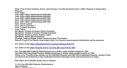
Goal How to Get Auxiliary Alarm and Trouble Contacts from a 2001 with 556 880 2001 2001 1007 Control Module 556 880 Unable to locate Alarm Contacts Need auxiliary alarm contact Need 24VDC for Relay operation Unable to locate Trouble Contacts Adding Digital Alarm Communicator Transmitter Adding auxiliary function to be tripped on alarm There are no relay outputs for this purpose Panel Modification will be required Modify the panel as below using an External Relay MR 101 or a 376 038 relay with a 442 039 base each function the coils of each relay to the points below Wire the Digital Alarm Communicator Transmitter to the relay output as required the 2001 has the Fire Control Module 556 880 for the proper contact outputs below Output on until Reset On the F Plug use pin 4 the far Left pin on the F Pug above the Fire Control Card for the positive Use Terminal 5 on the Left Hand Terminal Strip for the negative 2001 has 2 Trouble Busses that put the 2001 into trouble The Trouble Output for the 2001 has different points ON until silence or ON until cleared these are dependent to wiring with the Trouble Output ON until Silence 1 Use Terminal TB2 4 on the Right Hand Terminal Strip of Positive 2 Use Terminal TB1 5 on the Left Hand Terminal Strip for the Negative Trouble Output ON until Cleared if there is a connector in the C Socket below the Fire Control 1 Use Terminal 3 on the Annunciator Terminal Strip for the Positive 2 Use Terminal TB1 5 on the Left Hand Terminal Strip for the Negative If the Trouble Output needs to be on until cleared and there is no C Socket with an Annunciator strip then 2 relays are required for trouble monitoring The Trouble 6 Buss will have 24VDC when there is a internal trouble on the system The Trouble M Buss is a constant 24VDC and will out when a trouble occurs on external system components power supply chargers Use Terminal 3 on the Left Hand Terminal Strip for the Positive Trouble 6 Buss On the F Plug use pin M the far Right pin on the F Pug above the Fire Control Card for the Trouble M Buss Use Terminal 5 on the Left Hand Terminal Strip for the Negative


