Simplex IDNet Communicating Devices, External Addressable Manual Callpoint

File Preview
Click below to download for free
Click below to download for free
File Data
| Name | simplex-idnet-communicating-devices-external-addressable-manual-callpoint-2581039764.pdf |
|---|---|
| Type | |
| Size | 1.28 MB |
| Downloads |
Text Preview
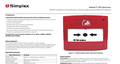
Features addressable manual fire alarm callpoint with Power and data supplied via IDNet addressable communications using single wire pair Enhanced aesthetics Designed for fast and easy installation Designed for EMI compatibility Surface mounting Test key allows the callpoint to be tested without breaking the glass Requires a special key to open the callpoint Simple snap fit to mounting box with Simplex Model series 4010 4100U 4007ES and 4100ES Communicating Devices External Addressable Manual Callpoints compact communications module installs easily to satisfy applications An integral individual addressable module IAM status and communicates changes to the connected control via IDNet communications 1 address per callpoint switch 8 position spade terminals and means type connections and operating range range protection H x W x D 3 5 8 in x 3 1 2 in x 2 7 8 in mm x 89 mm x 28 mm to 95 RH non condensing RAL3001 to 158 30 to 70 This product is not presently agency listed Contact your local product supplier for the latest status Manual Callpoint Communicating Devices External Addressable Manual Callpoint 1 Addressable Manual Callpoint of the Simplex callpoint requires the glass element to be Completing the action operates a micro switch whose condition signaled back to the control panel reset requires the use of a special key supplied with the to remove the front cover which allows the glass element to be testing occurs by inserting the key fully into the bottom of housing and pulling down This releases the bottom of the housing break glass element To reset the callpoint push the bottom of the upwards until it locks in position See Figure 2 2 Testing Rev 3 5 2020 Communicating Devices External Addressable Manual Callpoint Reference to NFPA 72 the National Fire Alarm Code and all applicable local codes for complete requirements for manual callpoints The following the basic requirements Callpoints are to be located in the normal path of exit and distributed in the protected area such that they are unobstructed and readily Mounting shall be with the operable part not less than 3 1 2 ft 1.1 m and not more than 4 1 2 ft 1.37 m above floor level At least one callpoint is to be provided on each floor Additional callpoints shall be provided to obtain a travel distance not more than 200 ft 61m the nearest callpoint from any part of the building When manual callpoint coverage appears limited in any way additional callpoints should be installed Selection Manual Callpoints with Internal IAM external English callpoint with LED Information replacement glass package of 10 Notes Mount the back box to a suitably flat surface using the three fixing holes and the screws provided in the installation pack The 20 mm cable entry holes should be in the vertical plane The back box can be mounted with either the single or the double entry holes at the top 3 information 2 Rev 3 5 2020 the Callpoint Address Communicating Devices External Addressable Manual Callpoint Callpoint to Backbox 4 the callpoint address 5 the callpoint to the backbox Ensure that the O ring is correctly seated in the channel on the rear of the cover Place the cover squarely over the back box and carefully push the cover until the locating clips have engaged Do not use excessive force The O ring should be replaced when refitting or replacing the Waterproof Cover is recommended that the 4 cover fixing screws are used to lock the cover into place 3 Rev 3 5 2020 Callpoint from Backbox Communicating Devices External Addressable Manual Callpoint To remove the cover undo and remove the 4 cover fixing screws Place the edge of a large flat bladed screwdriver into the slot between the cover and back box as shown right and gently twist until the latches are 6 the callpoint from the backbox Pull cover away from backbox the Break Glass Element 7 the Break Glass element 2020 Johnson Controls All rights reserved All specifications and other information shown were current as of document revision and are subject to change without Additional listings may be applicable contact your local Simplex product supplier for the latest status Listings and approvals under Simplex Time Recorder Co and the product names listed in this material are marks and or registered marks Unauthorized use is strictly prohibited NFPA 72 and National Fire Alarm Code are trademarks of the National Fire Protection Association NFPA Rev 3 5 2020