Simplex Install 4100 4120-Series MAPNET II Quad Isolator Module

File Preview
Click below to download for free
Click below to download for free
File Data
| Name | simplex-install-4100-4120-series-mapnet-ii-quad-isolator-module-9025718364.pdf |
|---|---|
| Type | |
| Size | 1.56 MB |
| Downloads |
Text Preview
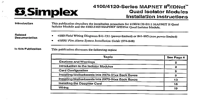
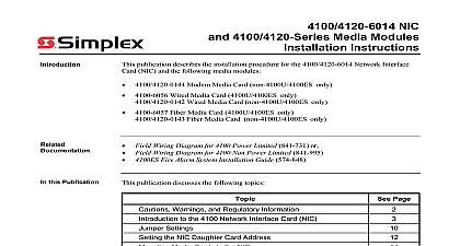
4100 4120 Series MAPNET II Quad Isolator Modules Instructions publication describes the installation procedure for 4100 4120 0111 MAPNET II Quad Module and the 4100 3103 MAPNET II IDNet Quad Isolator Module Models 0111 are intended for retrofit applications only Field Wiring Diagram for 4100 Power Limited 841 731 or Field Wiring Diagram for 4100 Non Power Limited 841 995 Fire Alarm System Installation Guide 574 848 this Publication publication discusses the following topics Page and Warnings to the Isolator Modules Configuration Motherboards into 2975 91xx Back Boxes 4100 Motherboards into 2975 94xx Back Boxes the Daughter Card 2005 2011 SimplexGrinnell LP All rights reserved and other information shown were current as of publication and are subject to change without notice and the Simplex logo are trademarks of Tyco International Ltd and its affiliates and are used under license F and Warnings and AND SAVE THESE INSTRUCTIONS Follow the instructions in this installation These instructions must be followed to avoid damage to this product and associated Product operation and reliability depend upon proper installation NOT INSTALL ANY SIMPLEX PRODUCT THAT APPEARS DAMAGED Upon your Simplex product inspect the contents of the carton for shipping damage If is apparent immediately file a claim with the carrier and notify an authorized product supplier HAZARD Disconnect electrical field power when making any internal adjust or repairs All repairs should be performed by a representative or authorized agent of local Simplex product supplier SAFETY HAZARD Under certain fiber optic application conditions the optical output this device may exceed eye safety limits Do not use magnification such as a microscope other focusing equipment when viewing the output of this device HAZARD Static electricity can damage components Handle as follows yourself before opening or installing components to installation keep components wrapped in anti static material at all times RULES AND REGULATIONS PART 15 This equipment has been tested and found to with the limits for a Class A digital device pursuant to Part 15 of the FCC Rules limits are designed to provide reasonable protection against harmful interference when equipment is operated in a commercial environment This equipment generates uses and radiate radio frequency energy and if not installed and used in accordance with the manual may cause harmful interference to radio communications Operation of equipment in a residential area is likely to cause harmful interference in which case the will be required to correct the interference at his own expense REACCEPTANCE TEST AFTER SOFTWARE CHANGES To ensure proper operation this product must be tested in accordance with NFPA72 1999 Chapter 7 any programming operation or change in site specific software Reacceptance testing is after any change addition or deletion of system components or after any repair or adjustment to system hardware or wiring components circuits system operations or software functions known to be affected by a must be 100 tested In addition to ensure that other operations are not affected at least 10 of initiating devices that are not directly affected by the up to a maximum of 50 devices must also be tested and proper system operation 2 to the Isolator Modules Information 4100 4120 0111 and 4100 3103 Quad Isolator Modules consist of two cards a motherboard mounts into either a CPU bay or an expansion bay and a daughter card that mount into the The 4100 4120 0111 and 4100 3103 Quad Isolator Modules are not compatible the IDNet Addressable Isolators General capabilities of the isolator module include Monitors and controls up to four loops The 4100 4120 0111 MAPNET II and 4100 MAPNET II or IDNet modules allow you to segment the entire MAPNET II or IDNet into four loops maximum Segmenting the channel simplifies troubleshooting and other devices to continue operating if a short circuit condition occurs on the MAPNET loop The isolator card takes up four card MAPNET II IDNet addresses Class A or Class B operation With Class A operation if an open occurs on any loop isolator module energizes an internal relay that enables the lines to carry the II or IDNet signal In Class B operation the faulty loop disconnects and the other continue to operate Short circuit disconnection The isolator module disconnects loops on which it senses a Loops that have shorts are continuously monitored and are automatically reconnected the short condition clears DOWN DOWN DOWN isolated output circuits the 4100 0111 Isolator 4100 3103 II or module Reference wires MAPNET II or and 24 VDC power MAPNET II or circuit circuit IDC or NAC zone IDC zone DOWN 1 MAPNET II Isolator Module Overview on next page 3 to the Isolator Modules Continued isolator operates in conjunction with the short circuit protection already present on the II or IDNet Interface Transceiver Board 562 976 On power up the transceiver tests portion of the line that it is protecting to see if any shorts exist If a short is detected the restricts power from flowing into that portion of the line on which the short was If a short is detected after power up the transceiver not the isolator shuts down the for 750 milliseconds The channel is then powered up and the isolator acts to isolate the line short circuit trouble clears when the short is removed from the lines The Class A fault will clear only when the fault condition is corrected and a System Reset has been initiated the 4100 operator interface panel addition to short circuit protection the isolator monitors a secondary wire pair for Class A If a break in any line is detected the Isolator switches communications onto both the and secondary pairs isolator can also be used to disconnect communication lines and shields from the transceiver aid in the location of earth troubles in the system as well as other installation problems This Isolation operation can only be accomplished from the operator interface panel isolator is regularly polled by the master controller to determine its current state If the does not respond this fact will be reported as a NO ANSWER trouble against that When the device IS communicating properly it will answer the poll with a normal circuit or open circuit response depending on the current hardware state of the system Correction Device Status check is made whenever a device is initialized If the device address location is incorrect the MAPNET II or IDNet transceiver will ignore status messages from the and will not send control messages to it isolator must be addressed at a valid MAPNET II or IDNet location and the job must be to recognize it on board LEDs LED 1 through LED 4 indicate the trouble state of the corresponding II or IDNet loop 32 F 0 C to 120 F 49 C 90 32 C degrees 93 Relative Humidity non condensing Current at 24V 4 Configuration section contains instructions on how to configure the card via DIP switches and jumpers The isolator is not a 4100 daughter card rather it is an IDNet slave There are three different types of IDNet cards 64 Point 127 Point and 250 Point Even though IDNet can support a maximum of 250 devices higher addresses be inaccessible because of the hardware used Be sure that you know the model of IDNet card that is connected to the isolator so that