Simplex Install Instructions 4100-6038 Dual RS-232 2120 Modules
File Preview
Click below to download for free
Click below to download for free
File Data
| Name | simplex-install-instructions-4100-6038-dual-rs-232-2120-modules-9415382670.pdf |
|---|---|
| Type | |
| Size | 1.78 MB |
| Downloads |
Text Preview
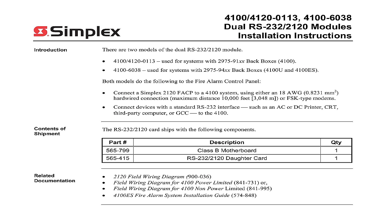
4100 6038 RS 232 2120 Modules Instructions used for systems with 2975 91xx Back Boxes 4100 used for systems with 2975 94xx Back Boxes 4100U and 4100ES are two models of the dual RS 232 2120 module models do the following to the Fire Alarm Control Panel Connect a Simplex 2120 FACP to a 4100 system using either an 18 AWG 0.8231 mm2 connection maximum distance 10,000 feet 3,048 m or FSK type modems Connect devices with a standard RS 232 interface such as an AC or DC Printer CRT computer or GCC to the 4100 of RS 232 2120 card ships with the following components B Motherboard Daughter Card Field Wiring Diagram 900 036 Field Wiring Diagram for 4100 Power Limited 841 731 or Field Wiring Diagram for 4100 Non Power Limited 841 995 Fire Alarm System Installation Guide 574 848 this Publication publication discusses the following topics Page and Warnings Jumpers Switches Motherboards into 2975 91xx Back Boxes 410079 Motherboards into 2975 94xx Back Boxes 4100U 4100ES the Daughter Card 2003 2011 SimplexGrinnell LP All rights reserved and other information shown were current as of publication and are subject to change without notice and the Simplex logo are trademarks of Tyco International Ltd and its affiliates and are used under license C and Warnings and AND SAVE THESE INSTRUCTIONS Follow the instructions in this installation These instructions must be followed to avoid damage to this product and associated Product operation and reliability depend upon proper installation NOT INSTALL ANY SIMPLEX PRODUCT THAT APPEARS DAMAGED Upon your Simplex product inspect the contents of the carton for shipping damage If is apparent immediately file a claim with the carrier and notify an authorized product supplier HAZARD Disconnect electrical field power when making any internal adjust or repairs All repairs should be performed by a representative or authorized agent of local Simplex product supplier HAZARD Static electricity can damage components Handle as follows yourself before opening or installing components to installation keep components wrapped in anti static material at all times RULES AND REGULATIONS PART 15 This equipment has been tested and to comply with the limits for a Class A digital device pursuant to Part 15 of the FCC These limits are designed to provide reasonable protection against harmful when the equipment is operated in a commercial environment This equipment uses and can radiate radio frequency energy and if not installed and used in with the instruction manual may cause harmful interference to radio Operation of this equipment in a residential area is likely to cause harmful in which case the user will be required to correct the interference at his own Jumpers Locations 1 shows the locations of the jumpers on the dual RS 232 2120 card and identifies the assigned to each jumper pin The specific jumper settings required on the dual card depend on the type of device being attached to the card Refer to Table 1 for jumper configurations s s 1 Location of Jumpers and Corresponding Pin Numbers on next page Jumpers Continued Settings for Devices 1 lists the jumper settings for the range of devices that can be attached to the RS 232 2120 to Figure 1 for the locations of the jumpers and their corresponding pin numbers In the below 2 3 means you should place the jumper on pins 2 and 3 whereas a designation of 1 2 you should place the jumper on pins 1 and 2 1 Jumper Settings for RS 232 2120 Devices Connected to Port A Connected to Port B DC COMM A Only Master Slave Port A Only Modem A Only Comm Standard Port A Only Printer Supervised Printer Unsupervised Printer CRT 3rd Party GCC Alert Supervised Printer CRT Switches SW1 on the RS 232 2120 card is a bank of eight DIP switches From left to right see 2 below these switches are designated as SW1 1 through SW1 8 The function of these is as follows SW1 1 This switch sets the baud rate for the internal 4100 communications line running the card and the 4100 CPU Set this switch to ON SW1 2 through SW1 8 These switches set the card address within the 4100 FACP to Table 2 for a complete list of the switch settings for all of the possible card addresses You must set these switches to the value assigned to the card by the Comm Rate SW 1 1 Be Set to Switches 1 2 through 1 8 the card address Figure 2 an Address of 3 Refer Table 2 for a list of settings 2 Address DIP Switch on next page Switches Continued 2 4100 Daughter Card Addresses 1 2 1 3 1 4 1 5 1 6 1 7 1 2 1 7 1 8