Simplex Installation 8-Volt DC-to-DC Converter
File Preview
Click below to download for free
Click below to download for free
File Data
| Name | simplex-installation-8-volt-dc-to-dc-converter-0839742156.pdf |
|---|---|
| Type | |
| Size | 781.63 KB |
| Downloads |
Text Preview
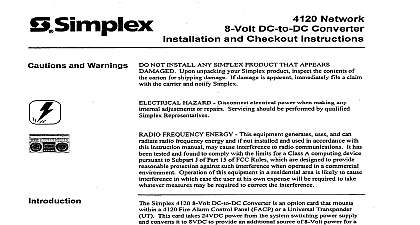
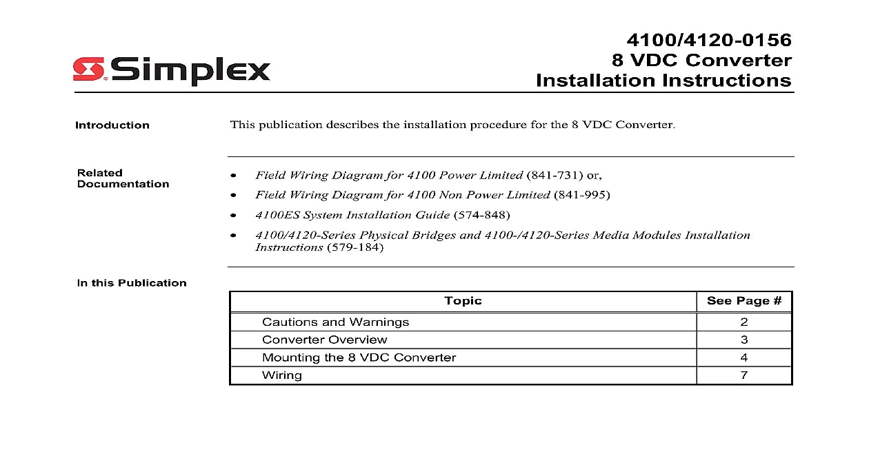
4100 4120 0156 VDC Converter Instructions publication describes the installation procedure for the 8 VDC Converter Field Wiring Diagram for 4100 Power Limited 841 731 or Field Wiring Diagram for 4100 Non Power Limited 841 995 System Installation Guide 574 848 Physical Bridges and 4100 4120 Series Media Modules Installation 579 184 this Publication Page and Warnings Overview the 8 VDC Converter 2004 2011 SimplexGrinnell LP All rights reserved and other information shown were current as of publication and are subject to change without notice and the Simplex logo are trademarks of Tyco International Ltd and its affiliates and are used under license E and Warnings and AND SAVE THESE INSTRUCTIONS Follow the instructions in this installation These instructions must be followed to avoid damage to this product and equipment Product operation and reliability depend upon proper NOT INSTALL ANY SIMPLEX PRODUCT THAT APPEARS DAMAGED Upon your Simplex product inspect the contents of the carton for shipping If damage is apparent immediately file a claim with the carrier and notify an Simplex product supplier HAZARD Disconnect electrical field power when making any internal or repairs All repairs should be performed by a representative or agent of your local Simplex product supplier SAFETY HAZARD Under certain fiber optic application conditions the optical of this device may exceed eye safety limits Do not use magnification such as a or other focusing equipment when viewing the output of this device HAZARD Static electricity can damage components Handle as follows Ground yourself before opening or installing components Prior to installation keep components wrapped in anti static material at all times RULES AND REGULATIONS PART 15 This equipment has been tested found to comply with the limits for a Class A digital device pursuant to Part 15 of FCC Rules These limits are designed to provide reasonable protection against interference when the equipment is operated in a commercial environment equipment generates uses and can radiate radio frequency energy and if not and used in accordance with the instruction manual may cause harmful to radio communications Operation of this equipment in a residential area likely to cause harmful interference in which case the user will be required to correct interference at his own expense REACCEPTANCE TEST AFTER SOFTWARE CHANGES To proper system operation this product must be tested in accordance with Chapter 7 after any programming operation or change in site specific Reacceptance testing is required after any change addition or deletion of components or after any modification repair or adjustment to system hardware wiring components circuits system operations or software functions known to be by a change must be 100 tested In addition to ensure that other operations not inadvertently affected at least 10 of initiating devices that are not directly by the change up to a maximum of 50 devices must also be tested and proper operation verified Overview Requirements 8 Volt DC to DC Converter is an option card that mounts within a 4100ES 4100U 4100 or Fire Alarm Control Panel FACP This card takes 24 VDC power from a system switching supply and converts it to 8 VDC The Converter is used when additional 8V power is for example when more than four Style 4 Physical Bridges are used 8 Volt DC to DC Converter has the following power requirements C PCB Black Connector position 1 24 V PCB Red Connector position 2 A max at 24V temperature 32 F to 120 F 0 C to 49 C 10 to 93 relative humidity at up to 90 F 32 C the 8 VDC Converter into the Back Box converter board and terminal block attachment are mounted onto a mounting plate the 4100 4120 the mounting plate gets attached to the side of an expansion bay with four so that the terminal block faces the front In the 4100U 4100ES the module must be to the backplane of an expansion bay following instructions apply to non 4100U 4100ES installations only If you are installing the into the 4100U 4100ES skip to the next section Remove AC power at the power source Locate the expansion bay that contains the Physical Bridge and remove the screw holding the restraint to the card retainer and set it aside Remove the two card retainer hinge pins and remove the card retainer Set the card retainer Remove two screws holding the left expansion bay bracket Figure 1 and remove the bracket pins aside the two screws aside Screws Expansion Bracket 1 Removing the Bracket on next page the 8 VDC Converter Continued into the Back Box Using three 426 047 Screws and 268 009 Lockwashers supplied secure the 8 Volt Converter to the 635 951 Expansion Bay End Bracket See Figure 2 The holes on the converter bracket may not align with the holes on some older of the Expansion Bay End Bracket In this case you must drill and tap for 6 32 mounting screws in the Expansion Bay End Bracket before the converter and Bracket 2 Mounting to the Bracket the bracket with the attached Converter on the left side of the bay using the two set aside in Step 8 Screws 3 Re Attaching the Bracket on next page the 8 VDC Converter Continued into the Back 4100U 4100ES converter assembly is secured to an expansion cabinet via two screws and as shown below USING TWO 441 002 SCREWS WASHERS 4 4100U 4100ES Mounting to Expansion Modules 9 10 The bay must be powered via the 636 818 Converter only Make certain other power or comms are wired to the bay Harness Assembly 733 940 plugs into pins 1 4 of P3 Expansion Bay End Bracket 635 951 Converter Assembly 636 818 rated for 3 A at 8 V nominal Harness Assembly 733 941 When a cabinet is used as a hub for physical bridges a dedicated physical bridge bay is required if four or Style 4 physical bridges are used A dedicated physical bridge bay is also required if three or more 7 physical bridges are used A Style 7 physical bridge requires two slots and a Style 4 physical bridge takes one of the eight available A maximum of six Style 4 bridges or four Style 7 bridges can be mounted in a bay A combination of Style 4 and Style 7 bridges can be mounted in the same bay The bay shown in this figure is dedicated for physical bridges only Other 4120 slaves including network cards may not be installed since slave comms are not wired to the bay When using the A tap of the CPU power supply connect the RED wire of the 733 941 Harness Assembly to Connect the BLACK wire of the 733 941 Harness Assembly to TB2 10 When using the B tap of the CPU power supply connect the RED wire of the 733 941 Harness Assembly TB2 8 Connect the BLACK wire of the 733 941 Harness Assembly to TB2 6 5 Connecting to Expansion Bay Modules 4100 on next page Continued to Expansion Modules The bay must be powered via the 637 549 Converter only Make certain other power or comms are wired to the bay Harness Assembly 733 940 plugs into pins 1 4 of P3 No modules in this bay connect to the PDI Converter Assembly 637 549 rated for 3 A at 8 V nominal Configure SPS NAC as Point Type AUXPWR When using SPS NACs for card power do not wire remote to SPS NACs A Style 7 physical bridge requires two slots and a Style 4 physical bridge takes one of the six remaining A maximum of six Style 4 bridges or three Style 7 bridges can be mounted in a bay A combination of Style 4 and