Simplex Installation Instructions 4100 4120-Series Media Module

File Preview
Click below to download for free
Click below to download for free
File Data
| Name | simplex-installation-instructions-4100-4120-series-media-module-1543726980.pdf |
|---|---|
| Type | |
| Size | 1.92 MB |
| Downloads |
Text Preview
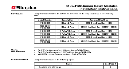
Introduction NIC 4100 4120 Series Media Modules Instructions publication describes the installation procedure for the 4100 4120 6014 Network Interface NIC and the following media modules Modem Media Card non 4100U 4100ES only Wired Media Card 4100U 4100ES only Wired Media Card non 4100U 4100ES only Fiber Media Card 4100U 4100ES only Fiber Media Card non 4100U 4100ES only Field Wiring Diagram for 4100 Power Limited 841 731 or Field Wiring Diagram for 4100 Non Power Limited 841 995 Fire Alarm System Installation Guide 574 848 this Publication publication discusses the following topics Page Warnings and Regulatory Information to the 4100 Network Interface Card NIC Settings the NIC Daughter Card Address Media Cards to the NIC Motherboards into 2975 91xx Back Boxes Non Motherboards into 2975 94xx Back Boxes the Daughter Card Procedure 2005 2011 SimplexGrinnell LP All rights reserved and other information shown were current as of publication and are subject to change without notice and the Simplex logo are trademarks of Tyco International Ltd and its affiliates and are used under license J Warnings and Regulatory Information AND SAVE THESE INSTRUCTIONS Follow the instructions in this installation These instructions must be followed to avoid damage to this product and associated Product operation and reliability depends upon proper installation NOT INSTALL ANY SIMPLEX PRODUCT THAT APPEARS DAMAGED Upon your Simplex product inspect the contents of the carton for shipping damage If is apparent immediately file a claim with the carrier and notify Simplex HAZARD Disconnect electrical field power when making any internal or repairs All repairs should be performed by a representative or an authorized agent you local Simplex product supplier HAZARD Static electricity can damage components Therefore handle as follows Ground yourself before opening or installing components Prior to installation keep components wrapped in anti static material at all times SAFETY HAZARD Under certain fiber optic application conditions the optical output of device may exceed eye safety limits Do not use magnification such as a microscope or other equipment when viewing the output of this device RULES AND REGULATIONS PART 15 This equipment has been tested and found comply with the limits for a Class A digital device pursuant to Part 15 of the FCC Rules These are designed to provide reasonable protection against harmful interference when the is operated in a commercial environment This equipment generates uses and can radio frequency energy and if not installed and used in accordance with the instruction may cause harmful interference to radio communications Operation of this equipment in residential area is likely to cause harmful interference in which case the user will be required to the interference at his own expense REACCEPTANCE TEST AFTER SOFTWARE CHANGES To ensure proper operation this product must be tested in accordance with NFPA72 1996 Chapter 7 after programming operation or change in site specific software Reacceptance testing is required any change addition or deletion of system components or after any modification repair or to system hardware or wiring components circuits system operations or software functions known to be affected by a must be 100 tested In addition to ensure that other operations are not inadvertently at least 10 of initiating devices that are not directly affected by the change up to a of 50 devices must also be tested and proper system operation verified Introduction to the 4100 Network Interface Card NIC Network Interface Card NIC is a slave card that uses the standard 4100 serial bus to with the master The NIC connects FACPs in a network allowing for between each panel via fiber modem or twisted shielded pair wire in a Style 7 configuration NIC is designed to be connected in a point to point arrangement so that one wire fault does cause the entire system to fail The point to point arrangement provides the most secure and wiring possible types of media boards can be used with the NIC The Fiber Optic Media Card can be used for electrically noisy environments or for externally to other buildings Non 4100U 4100ES only the Modem Media Card is typically used when a large distance is required The Wired Media Card is used in all other types of applications to two media boards can be plugged into each NIC The same NIC can use a combination of types of media boards for example a NIC may have a wired media card connected to port 1 a fiber optic media card connected to port 2 on next page to the 4100 Network Interface Card NIC Continued 1 depicts the 4100 6014 Network Interface Card TRANSMIT LEDs THROUGH CARD P6 RATE JUMPER P3 PORT DIP SW2 LED SWITCH P4 Card LED 1 4100 6014 Network Interface Card with the 4100 master 4100 6014 NIC module has the following LEDs yellow Illuminates when the NIC has not established a communications red Illuminates when a data is received at the right port green Illuminates when a data is transmitted at the right port red Illuminates when a data is received at the left port green Illuminates when a data is transmitted at the left port on next page to the 4100 Network Interface Card NIC Continued Card LED figures below are illustrations of three motherboards apart from the default CPU motherboard can be used with the 4100 NIC The 565 274 Master Motherboard holds two daughter cards the 4100 master controller and the 4100 NIC The 565 275 Class B Motherboard holds the 4100 NIC by itself The 566 227 4100U 4100ES Master Motherboard holds a CPU card and NIC WIRING TB1 BUS J3 CONNECT P4 MASTER J2 COMM RS 232 CARD J1 COMMS P2 BUS P1 POWER P3 WIRING TB2 2 UT Motherboard with City Connection 565 274 WIRING TERMINAL TB1 COMM RS 232 CARD J1 COMMS P2 BUS P1 POWER P3 WIRING TB2 3 Class B Motherboard 565 275 on next page to the 4100 Network Interface Card NIC Continued RSRVD R GND 0V 1 SHLD CTS GND WIRED MEDIA RS 232 BLOCK TB3 PORT 1 P10 CONNECTOR TO MOTHERBOARD CONNECTOR TO MOTHERBOARD CONNECTOR TO MOTHERBOARD DAUGHTER CARD PORT 2 P11 WIRED MEDIA RS 232 BLOCK TB1 24C RSRVD 4 4100U 4100ES CPU Master Motherboard TERMINAL BLOCK TB2 COMM SHIELD P9 TO POWER P1 CLASS A LED1 PRIMARY SHORT LED2 SECONDARY TROUBLE CONNECTOR Reserved for use DAUGHTER CARD J3 TO B