Simplex Installation Instructions 4100-5124 Class A Adapter Card

File Preview
Click below to download for free
Click below to download for free
File Data
| Name | simplex-installation-instructions-4100-5124-class-a-adapter-card-8352716904.pdf |
|---|---|
| Type | |
| Size | 900.83 KB |
| Downloads |
Text Preview
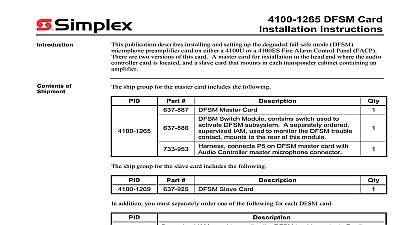
Introduction Class A Adapter Card Instructions publication describes the installation procedure for the 4100 5124 Class A Adapter Card card mounts to a TrueAlert Power Supply TPS and converts the three standard Class B Line Circuits SLCs on the TPS to Class A SLCs to the 4100 5120 5121 5124 TrueAlert Power Supply Installation Instructions 579 336 for on installing the TPS and wiring Class A SLCs Contents Shipment unpacking your Simplex product inspect the contents of the carton for shipping damage If is apparent immediately file a claim with the carrier and notify Simplex this Publication publication discusses the following topics and Warnings to the TPS Page 2001 2011 SimplexGrinnell LP All rights reserved and other information shown were current as of publication and are subject to change without notice and the Simplex logo are trademarks of Tyco International Ltd and its affiliates and are used under license B and Warnings and AND SAVE THESE INSTRUCTIONS Follow the instructions in this installation These instructions must be followed to avoid damage to this product and associated Product operation and reliability depend upon proper installation NOT INSTALL ANY SIMPLEX PRODUCT THAT APPEARS DAMAGED Upon your Simplex product inspect the contents of the carton for shipping damage If is apparent immediately file a claim with the carrier and notify an authorized product supplier HAZARD Disconnect electrical field power when making any internal adjust or repairs All repairs should be performed by a representative or authorized agent of local Simplex product supplier HAZARD Static electricity can damage components Handle as follows yourself before opening or installing components to installation keep components wrapped in anti static material at all times SAFETY HAZARD Under certain fiber optic application conditions the optical output this device may exceed eye safety limits Do not use magnification such as a microscope other focusing equipment when viewing the output of this device RULES AND REGULATIONS PART 15 This equipment has been tested and found to with the limits for a Class A digital device pursuant to Part 15 of the FCC Rules limits are designed to provide reasonable protection against harmful interference when equipment is operated in a commercial environment This equipment generates uses and radiate radio frequency energy and if not installed and used in accordance with the manual may cause harmful interference to radio communications Operation of equipment in a residential area is likely to cause harmful interference in which case the will be required to correct the interference at his own expense REACCEPTANCE TEST AFTER SOFTWARE CHANGES To ensure proper system this product must be tested in accordance with NFPA 72 after any programming or change in site specific software Reacceptance testing is required after any addition or deletion of system components or after any modification repair or to system hardware or wiring components circuits system operations or software functions known to be affected by a must be 100 tested In addition to ensure that other operations are not affected at least 10 of initiating devices that are not directly affected by the up to a maximum of 50 devices must also be tested and proper system operation 72 is a registered trademark of the National Fire Protection Association 4100 5124 Class A Adapter Card mounts to the TPS using four hex standoffs standoffs have threaded male and female ends these steps to mount the Class A Adapter Card Remove the two Torx screws shown in Figure 1 The holes in which the screws installed are used for the Class A board standoffs the threaded male end of the hex standoff in one of the standoff holes on TPS Fully screw the standoff into the threaded hole Repeat this step for other three holes end Standoff these 1 Location of Standoff Holes on TrueAlert Power Supply Place the Class A Adapter Card on the standoffs Align the holes on the card the holes on the top of the standoffs Secure the card to the standoffs with screws to the TPS Threaded end of into Holes Text B