Simplex Installation Instructions 4100-6030 Service Modem
File Preview
Click below to download for free
Click below to download for free
File Data
| Name | simplex-installation-instructions-4100-6030-service-modem-3754160298.pdf |
|---|---|
| Type | |
| Size | 697.09 KB |
| Downloads |
Text Preview
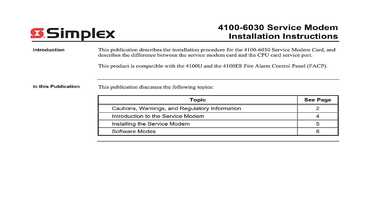
4100 6030 Service Modem Instructions publication describes the installation procedure for the 4100 6030 Service Modem Card and the difference between the service modem card and the CPU card service port product is compatible with the 4100U and the 4100ES Fire Alarm Control Panel FACP this Publication publication discusses the following topics Page Warnings and Regulatory Information to the Service Modem the Service Modem Modes 2005 2011 SimplexGrinnell LP All rights reserved and other information shown were current as of publication and are subject to change without notice and the Simplex logo are trademarks of Tyco International Ltd and its affiliates and are used under license E Warnings and Regulatory Information and AND SAVE THESE INSTRUCTIONS Follow the instructions in this installation These instructions must be followed to avoid damage to this product and associated Product operation and reliability depend upon proper installation NOT INSTALL ANY SIMPLEX PRODUCT THAT APPEARS DAMAGED Upon your Simplex product inspect the contents of the carton for shipping damage If is apparent immediately file a claim with the carrier and notify an authorized product supplier HAZARD Disconnect electrical field power when making any internal adjust or repairs All repairs should be performed by a representative or authorized agent of local Simplex product supplier HAZARD Static electricity can damage components Handle as follows yourself before opening or installing components to installation keep components wrapped in anti static material at all times You May to Provide to Telephone requested by the telephone company the following information must be provided before the service modem to telephone lines Original Manufacturer Simplex Time Recorder Company Model Number 4100 6030 Compliance FCC Part 68 Rules Type of Jack s to be installed by the telephone company RJ 31X Type of Connector s RJ 11 on next page Warnings and Regulatory Information Continued of Federal Communications Commission FCC has established specifications that permit this to be directly connected to the telephone network Time Recorder Simplex Drive MA 01441 that the Simplex Model 4100 6030 Service Modem Cards conform to the FCC 15 is subject to the following two conditions This device may not cause harmful electromagnetic interference and This device must accept any interference received including interference that may cause operation 68 equipment complies with FCC Rules Part 68 A label containing the FCC Registration and the Ringer Equivalence Number REN is located on the top of the Fire Alarm Panel cabinet in which this card is installed You must provide this information to the company when requested REN is used to determine the number of devices that you may legally connect to your lines In most areas the sum of the REN of all devices connected to one line must not five 5.0 You should contact your telephone company to determine the maximum REN your calling area equipment uses the following USOC plug RJ 11 equipment may not be used on party lines or on coin service provided by the telephone FCC compliant telephone cord and modular plug are available for this equipment which is to connect to the telephone network or premises wiring using a Part 68 compliant jack See installation instructions for details Introduction to the Service Modem 4100 6030 Service Modem is an option card that can be attached to the CPU board The modem provides support for remote access to PCs 1 below is an illustration of the service modem CONNECTOR TELEPHONE LINE BOARD reverse side TRANSMIT LED RECEIVE LED 1 The Service Modem Modem LED service modem has the following LEDs 2 Illuminates when the modem receives data 4 Illuminates when the modem is transmitting data 1 lists the service modem specifications 1 Specifications Specifications Operating C 32 F to 49 C 120 F relative humidity non condensing at 32 C 90 F the Service Modem section describes the mounting procedure for the service modem and a guideline as to how to to a computer service modem mounts on the CPU daughter card Use the following instructions to mount service modem to the CPU card Attach the metal standoff 524 253 with a nut 322 122 to the CPU card Secure the modem to the CPU card with the plastic standoffs as shown in Figure 2 At the time connect P4 on the CPU card to P1 on the modem Attach a ground wire to the service modem above the metal standoff with a screw Connect the ground wire to the backplane of the FACP chassis CARD P4 CARD P1 STANDOFF SCREW WIRE MODEM CARD AREA to Computer CARD 2 Mounting the Service Modem RJ 11 port is provided on the service modem for a standard phone line connection to the PC remote PC must be set up with its own modem for the connection to operate HyperTerminal parameters must be set as follows VT100 VT220 Rate 19,200 Bits 8 None Bits 1 Control None Type Standard to the corresponding chapter in the ES Panel Programmer Manual 574 849 for further a DACT is installed the RJ 11 port can be connected to TELCO line 2 TB1 on house R2 T2 terminals This eliminates the need for a third phone line Modes Modes FACP can connect to PCs running important utilities such as diagnostics programming CPU downloading and channel monitoring It connects to PCs running all of these utilities the service port on the CPU daughter card When a PC is located remotely from the FACP the Service Modem is used are three basic software modes that the service port or service modem can be used to to Service and Diagnostics Mode Data Transfer Interface Mode Master Bootloader Interface Mode mode is described below and Diagnostics Mode The default functionality when a PC is connected to the FACP a PC this mode provides application startup messages an ASCII interface to a UI command for diagnostics and event reporting The PC must be running terminal emulation software to a PC is made via serial port or service modem FD9 194 01 2 1 download running emulation software Panel with CPU modem card application running emulation software 3 Service and Diagnostic Interface Transfer Interface Mode In this mode the FACP Programmer is enabled This allows for downloading as well as downloading a configuration and audio messages to the FACP and a configuration or history log from the FACP Connection to a PC is made via serial or service modem FD9 194 02 2 1 download running software Panel with CPU modem card application running software 4 Data Transfer Interface on next page Modes Continued Modes Bootloader Interface Mode This mode downloads the Master CPU Exec firmware and CFG TXT file to the CPU via the serial port FD9 194 03 download running running emulation software file transfer Panel Bootloader 5 Bootl