Simplex Installation Instructions LED Switch Modules

File Preview
Click below to download for free
Click below to download for free
File Data
| Name | simplex-installation-instructions-led-switch-modules-4250831796.pdf |
|---|---|
| Type | |
| Size | 993.31 KB |
| Downloads |
Text Preview
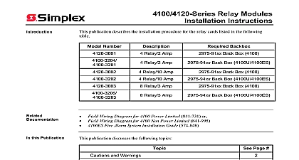
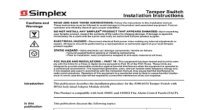
Modules Instructions publication describes the installation procedure for the 4100 1288 LED Switch Controller and the associated 4100 1275 to 4100 1280 to 4100 1295 4100 1296 and to 1302 LED Switch Modules product is compatible with 4100U and 4100ES Fire Alarm Control Panels FACP this Publication publication discusses the following topics Page and Warnings LED Switch User Interface 1 Configuring the LED Switch Controller Card 2 Mounting 3 Interconnecting Cards Switch and LED Mapping for Programmer 2001 2011 SimplexGrinnell LP All rights reserved and information shown were current as of publication and are subject to change without notice and the Simplex logo are trademarks of Tyco International Ltd and its affiliates and are used under license K and Warnings and AND SAVE THESE INSTRUCTIONS Follow the instructions in this installation These instructions must be followed to avoid damage to this product and associated Product operation and reliability depend upon proper installation NOT INSTALL ANY SIMPLEX PRODUCT THAT APPEARS DAMAGED Upon your Simplex product inspect the contents of the carton for shipping damage If is apparent immediately file a claim with the carrier and notify an authorized product supplier HAZARD Disconnect electrical field power when making any internal adjust or repairs All repairs should be performed by a representative or authorized agent of local Simplex product supplier SAFETY HAZARD Under certain fiber optic application conditions the optical output this device may exceed eye safety limits Do not use magnification such as a microscope other focusing equipment when viewing the output of this device HAZARD Static electricity can damage components Handle as follows yourself before opening or installing components to installation keep components wrapped in anti static material at all times RULES AND REGULATIONS PART 15 This equipment has been tested and to comply with the limits for a Class A digital device pursuant to Part 15 of the FCC These limits are designed to provide reasonable protection against harmful when the equipment is operated in a commercial environment This equipment uses and can radiate radio frequency energy and if not installed and used in with the instruction manual may cause harmful interference to radio Operation of this equipment in a residential area is likely to cause harmful in which case the user will be required to correct the interference at his own REACCEPTANCE TEST AFTER SOFTWARE CHANGES To ensure system operation this product must be tested in accordance with NFPA72 1996 7 after any programming operation or change in site specific software testing is required after any change addition or deletion of system components after any modification repair or adjustment to system hardware or wiring components circuits system operations or software functions known to be affected by a must be 100 tested In addition to ensure that other operations are not affected at least 10 of initiating devices that are not directly affected by the up to a maximum of 50 devices must also be tested and proper system operation LED Switch User Interface LED switch user interface consists of a variety of display modules mounted to the front of a which are configured via the FACP Programmer Each display module contains between 8 24 switches and LEDs each one separately configurable Interface functionality is driven by the LED Switch Controller Card which mounts behind of the display cards The varieties of modules are as follows LED Switch Controller Card with mounting plate LED Switch Controller Card no mounting plate mounts on extra space of 8 Switch 8 LED Display Card With red LEDs 8 Switch 8 LED Display Card With yellow LEDs 8 Switch 16 LED Display Card With one red and one yellow LED per 8 Switch 16 LED Display Card With two yellow LEDs per switch 8 Switch 16 LED Display Card With one red and one green LED per switch 16 Switch 16 LED Display Card With red LEDs Hand Off Auto HOA Switch Display Card Provides 24 switches and 24 The HOA uses an overlay to group every 3 switches together denoting on off automatic control of smoke control components For every group of 3 switches there 3 LEDs green red green 24 Switch 24 LED Display Card With red LEDs Hand Off Auto HOA IBC with Green Red White LED SW Module Eight in a double slot module Each control has three switches and three LEDs for selection LED color designation meets the International Building Code IBC Hand Off Auto HOA IBC with Green Red White LED SW Module No Same as 4100 1275 except switches are unlabeled 2 Blank display cover module to cover empty front panel space Slide In Label Kit one per FACP cabinet 8 Pluggable LEDs with 8 red LEDs 16 Pluggable LEDs with alternating red and yellow LEDs 16 Switch 16 LED with alternating red and yellow LEDs one per switch Hand Off Auto HOA with Green Red Green LED SW Module No Text as 4100 1286 except switches are unlabeled 8 Switch 16 LED Display Card With one green and one yellow LED per 16 Pluggable LED 16 Switch Module RED YEL HOA Module w 24 SW 24 GRN YEL GRN LEDs No text HOA Module w 24 SW 24 GRN YEL GRN LEDs Pluggable LED Kit 8 Yellow LEDs Pluggable LED Kit 8 Green LEDs Pluggable LED Kit 8 Red LEDs Pluggable LED Kit 8 Blue LEDs on next page LED Switch User Interface Continued Card LED switch controller card is an FACP slave that is intended to mount behind a user interface card The LED switch controller handles up to 64 switches and 64 LEDs on the UI cards and their status to the FACP CPU When a button is pressed on a UI card the acknowledges the signal and reacts according to how that switch was configured via the DISPLAY reverse side LOSS LED LED1 DIP SW1 ANNUNCIATOR P1 1 LED Switch Controller on next page LED Switch User Interface Continued Card Cards more than 64 LEDs or 64 switches are used a second controller may be installed 1 This LED illuminates if communication loss between the controller and the CPU occurs is independent of jumper P1 which configures different communication loss features types of display cards are mounted to the front of a cabinet and are connected to each other a ribbon cable Each display card operates by the same rules when a button is pressed the card sends the CPU the information and the event programmed for that button occurs 1 LED Switch Module Specifications Specifications for LED Switch Controller voltage current no LEDs on current with LEDs ON VDC 19 to 33 VDC mA max over range 2.5 mA per LED on at 24 VDC for a total of 180 mA for 64 LEDs ON 3.0 mA per LED on at 19 VDC for a total of 212 mA for 64 LEDs ON Specifications for All LED Switch Modules temperature to 120 F 0 to 49 C non condensing 32 C 90 F 1 Configuring the LED Switch Controller Card the Feature the Address LED switch controller is the only user interface module that requires physical configuration consists of setting jumper P1 and setting the device address the LED switch controller is used in a remote annunciator you must make the