Simplex Installation Instructions Redundant Master Controller
File Preview
Click below to download for free
Click below to download for free
File Data
| Name | simplex-installation-instructions-redundant-master-controller-4091327586.pdf |
|---|---|
| Type | |
| Size | 1.10 MB |
| Downloads |
Text Preview
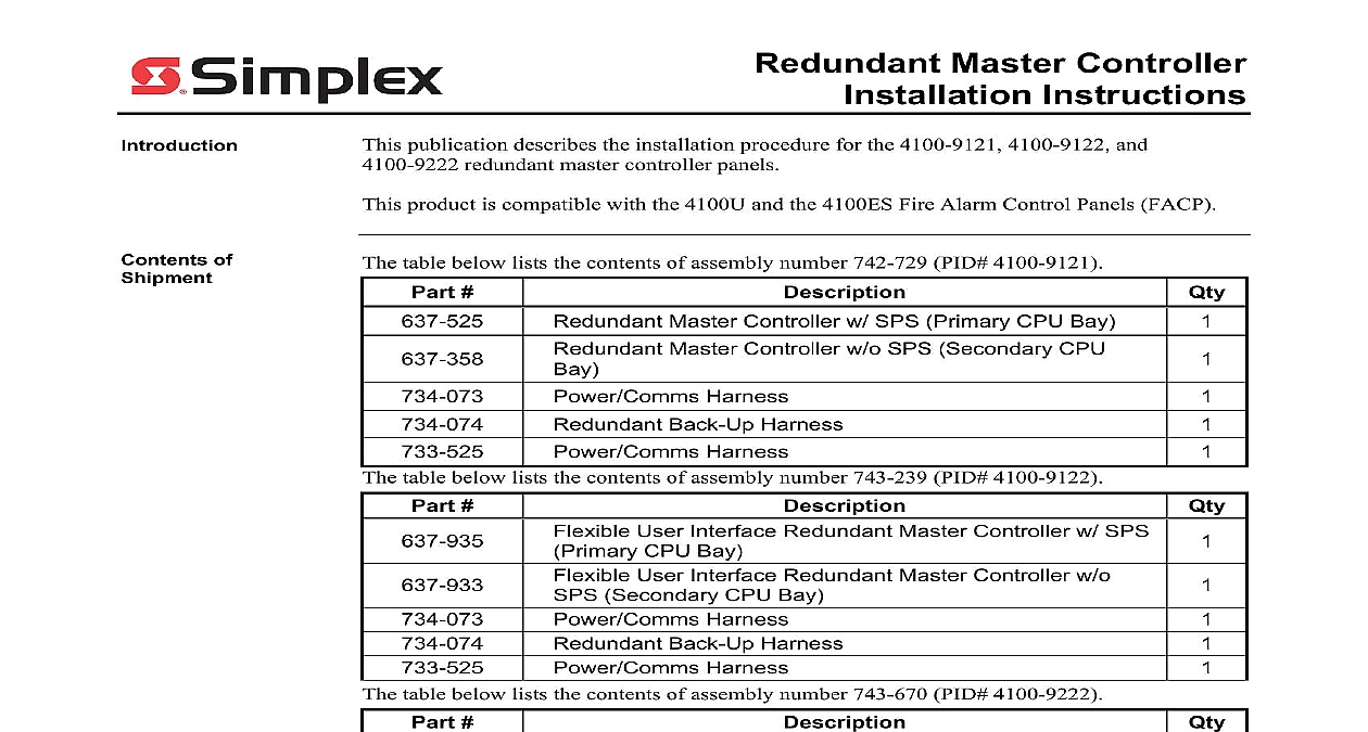
Redundant Master Controller Instructions publication describes the installation procedure for the 4100 9121 4100 9122 and redundant master controller panels product is compatible with the 4100U and the 4100ES Fire Alarm Control Panels FACP table below lists the contents of assembly number 742 729 PID 4100 9121 of table below lists the contents of assembly number 743 239 PID 4100 9122 Master Controller w SPS Primary CPU Bay Master Controller w o SPS Secondary CPU Harness Back Up Harness Harness User Interface Redundant Master Controller w SPS CPU Bay User Interface Redundant Master Controller w o Secondary CPU Bay Harness Back Up Harness Harness User Interface Redundant Master Controller w SPS CPU Bay User Interface Redundant Master Controller w o Secondary CPU Bay Harness Harness CPU Harness The table below lists the contents of assembly number 743 670 PID 4100 9222 of Contents Page and Warnings Description the Back Box the PDM in the Back Box System Components the CPU Bays Power to the System A System Power Supply Specifications B Device Configuration DIP Switch 2006 2011 SimplexGrinnell LP All rights reserved and other information shown were current as of publication and are subject to change without notice and the Simplex logo are trademarks of Tyco International Ltd and its affiliates and are used under license J and Warnings and AND SAVE THESE INSTRUCTIONS Follow the instructions in this installation These instructions must be followed to avoid damage to this product and associated Product operation and reliability depend upon proper installation NOT INSTALL ANY SIMPLEX PRODUCT THAT APPEARS DAMAGED Upon your Simplex product inspect the contents of the carton for shipping damage If is apparent immediately file a claim with the carrier and notify an authorized product supplier HAZARD Disconnect electrical field power when making any internal adjust or repairs All repairs should be performed by a representative or authorized agent of local Simplex product supplier HAZARD Static electricity can damage components Handle as follows yourself before opening or installing components to installation keep components wrapped in anti static material at all times SAFETY HAZARD Under certain fiber optic application conditions the optical output this device may exceed eye safety limits Do not use magnification such as a microscope other focusing equipment when viewing the output of this device RULES AND REGULATIONS PART 15 This equipment has been tested and found to with the limits for a Class A digital device pursuant to Part 15 of the FCC Rules limits are designed to provide reasonable protection against harmful interference when equipment is operated in a commercial environment This equipment generates uses and radiate radio frequency energy and if not installed and used in accordance with the manual may cause harmful interference to radio communications Operation of equipment in a residential area is likely to cause harmful interference in which case the will be required to correct the interference at his own expense REACCEPTANCE TEST AFTER SOFTWARE CHANGES To ensure proper system this product must be tested in accordance with NFPA 72 after any programming or change in site specific software Reacceptance testing is required after any addition or deletion of system components or after any modification repair or to system hardware or wiring components circuits system operations or software functions known to be affected by a must be 100 tested In addition to ensure that other operations are not affected at least 10 of initiating devices that are not directly affected by the up to a maximum of 50 devices must also be tested and proper system operation 72 is a registered trademark of the National Fire Protection Association Description 4100U and the 4100ES product lines support the option for a redundant master controller This is achieved through the use of two CPU bays a primary and a secondary The bay contains the primary CPU and the additional controller cards necessary to switch to secondary CPU if a trouble occurs The system power supply SPS is located in the primary bay secondary CPU bay houses the secondary CPU that is mounted to a two inch wide class B Figure 1 shows a typical layout of the components within an FACP with a Master Controller More specific details pertaining to each bay are discussed later in section 4100 9121 includes the standard 2x40 operator interface while the 4100 9122 and 4100 9222 of the redundant master controller includes a Flexible User Interface The Flexible User is a front panel assembly that features a large screen display instead of the standard 2x40 FD9 331 01 Bay Power Supply Box 1 2 3 4 Module Wiring Wiring Bay PDI Power Boards Slot Boards Slot Module Wiring 1 Primary and Secondary CPU Bays two bays are shipped together with all necessary components installed The procedure for the redundant master controller is to install a back box assembly shipped separately the PDM shipped separately and electronics bays to the back box interconnect the bays wire AC power and batteries to the system on next page Description Continued Primary Bay primary CPU bay in the redundant master controller configuration see Figure 2 contains a motherboard with an attached CPU daughter card or master controller CPU switcher card adjacent to the CPU motherboard is the relay card that switches the bus from the primary CPU card to the CPU card in the secondary CPU bay The Point I O card monitors the communications with the primary CPU SPM1 on the 24 Point I O shorted via factory wiring to program the 24 Point I O for communications monitoring In the of failure of the primary CPU the 24 Point I O card activates I O point 1 I O point 1 is to the CPU Switcher card via harness A relay on board the CPU Switcher card transfers communications from the Primary CPU to the Secondary CPU All slave cards and modules the FACP system must be wired to the right of slot 3 or in another bay wired after the CPU FD9 331 02 Switcher Point I O Slot is not used network card in a after the CPU in bay 2 or another Daughter Card Controller POWER SPS 2 Primary CPU Bay Configuration or RELAY on next page Description Continued Primary CPU 3 shows the entire primary CPU bay assembly with a 2 x 40 2 lines of 40 characters each interface Figure 4 shows the entire primary CPU bay assembly with a Flexible User All of the preinstalled components within the bay are shown in the illustration Motherboard Switcher Card x 40 Operator Interface User Interface Daughter Card Controller I O Card Power SPS Daughter Card Controller I O Card Power SPS 3 Primary CPU Bay 4100 9121 Model Shown Motherboard Switcher Card 4 Primary CPU Bay 4100 9122 Model Shown on next page Description Continued Secondary Bay secondary CPU bay in the redundant master controller configuration see Fig