Simplex Installation Instructions Remote Display Assembly
File Preview
Click below to download for free
Click below to download for free
File Data
| Name | simplex-installation-instructions-remote-display-assembly-3056187492.pdf |
|---|---|
| Type | |
| Size | 976.91 KB |
| Downloads |
Text Preview
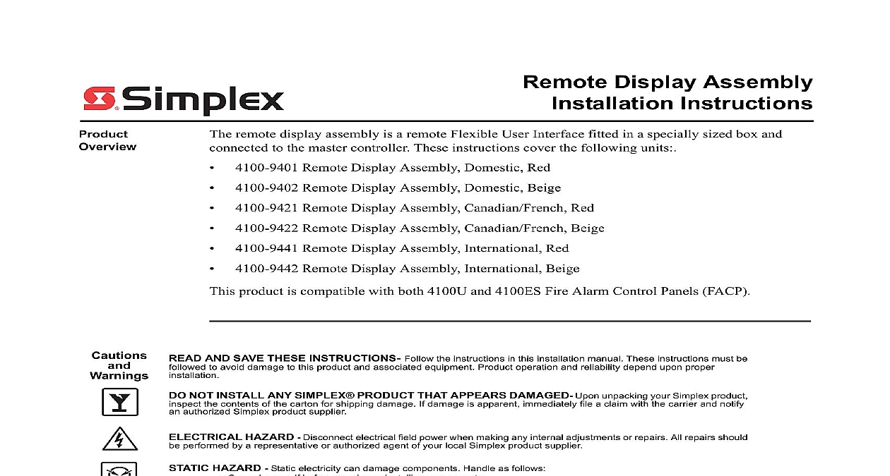
Remote Display Assembly Installation Instructions remote display assembly is a remote Flexible User Interface fitted in a specially sized box and to the master controller These instructions cover the following units Remote Display Assembly Domestic Red Remote Display Assembly Domestic Beige Remote Display Assembly Canadian French Red Remote Display Assembly Canadian French Beige Remote Display Assembly International Red Remote Display Assembly International Beige product is compatible with both 4100U and 4100ES Fire Alarm Control Panels FACP AND SAVE THESE INSTRUCTIONS Follow the instructions in this installation manual These instructions must be to avoid damage to this product and associated equipment Product operation and reliability depend upon proper NOT INSTALL ANY SIMPLEX PRODUCT THAT APPEARS DAMAGED Upon unpacking your Simplex product the contents of the carton for shipping damage If damage is apparent immediately file a claim with the carrier and notify authorized Simplex product supplier HAZARD Disconnect electrical field power when making any internal adjustments or repairs All repairs should performed by a representative or authorized agent of your local Simplex product supplier HAZARD Static electricity can damage components Handle as follows Ground yourself before opening or installing components Prior to installation keep components wrapped in anti static material at all times This document covers the following subjects the Remote Display Assembly the Remote Display Assembly the Remote Display Assembly instructions on programming the Flexible User Interface refer to the ES Panel Programmer 574 849 2006 2011 SimplexGrinnell LP All rights reserved and other information shown were current as of publication and are subject to change without notice and the Simplex logo are trademarks of Tyco International Ltd and its affiliates and are used under license D to the following environmental and power specifications Draw mA Normal Standby mA alarm to 120oF 0 to 49oC to 93 non condensing relative humidity at 90oF 32oC remote display assembly RDA is a surface mounted version of the Flexible User Interface The is mounted remotely from the FACP and wired back to it via remote unit interface RUI wiring the printed circuit boards and LCD are factory installed within the RDA enclosure hardware consists of surface mounting the enclosure to the wall and completing the RUI circuit The 4100 9401 Flexible User Interface remote display assembly contains the following User Interface panel assembly transponder interface card TIC box 13 INTERFACE USER PANEL BOX DOOR Figure 1 4100 9401 Flexible User Interface Remote Display Assembly continued User Board Flexible User Interface Controller Board has three main functions it stores and runs the control used to manage the display communicates with the FACP master controller via internal or RUI and processes front panel operator input User Panel 1 6 Figure 2 Flexible User Interface Controller Board Components Flexible User Interface controller board components include 1 6 to P2 on Flexible User Interface keyboard using harness 166 226 to P3 on Flexible User Interface keyboard using harness 166 226 to LCD with matching connector to LCD to provide power direct connection of PC to Flexible User Interface controller for down fonts and MSGLIB information Flexible User Interface is installed in the master controller cabinet use harness to connect P7 or P9 on the Flexible User Interface controller with either P5 or P6 on the CPU motherboard Flexible User Interface is installed in remote cabinet use harness 734 008 to P7 or P9 on the controller with P2 on the transponder interface card to 637 909 memory add on module backlight intensity screen contrast FACP address and communications baud rate controller card communication status with master continued Card transponder interface card housed in the Flexible User Interface remote display assembly is a varia of the TICs used in the FACP Miniplex and follows the same wiring guidelines as the Miniplex Refer to 574 848 4100ES Fire Alarm System Installation Guide for the TIC wiring guidelines 4 5 SCREW SCREW 1 2 1 2 4 5 Figure 3 Transponder Interface Card transponder interface card includes the following components communication loss with FACP Master when lit when a RUI ground fault search is active to indicate an RUI Style 7 primary trouble to indicate an RUI Style 7 secondary trouble harness 734 008 to connect to either P7 or P9 on the Flexible User Interface card the RUI address for the card to the master controller to power the remote display assembly to FACP master through RUI wiring the Remote Display Assembly the Box order to install the RDA the back box must be prepared for installation The contents of the box must removed and a wiring hole must be drilled into the back of the box 1 Unscrew the grounding wire from the door of the box The wire is held in the inside top right corner the door by a nut and washer the hinge 2 Remove the door from the box The door sits on the hinge and must be lifted in order to separate it 3 Locate the panel release tabs that extend past the top corners of the Flexible User Interface Press the panel release tabs in and pull the Flexible User Interface panel assembly The panel is now set perpendicularly to the back box 4 Remove all wires and cables connecting the panel to either the back box or the TIC The harness the TIC to the controller card can be unplugged by pressing the tab at the end of the The nut and washer holding the grounding cable must be unscrewed 5 To completely remove the panel press the latches at the bottom of the assembly in and lift the door off the swivel standoffs extending from the side of the bay See Figure 8 6 Remove the nuts and washers from the corners of the TIC module the card and the sheet metal and remove the module the TIC to the Master 7 Drill a 1 2 inch diameter wiring hole through the back of the box above the TIC This serves to 8 File the drilled location to remove any sharp edges before running any field wiring through the the Box 4 specifies the dimensions of the remote box and identifies the location of the mounting holes the instructions below to install the remote box MM MM MOUNTING Figure 4 Remote Display Unit Dimensions the Remote Display Assembly continued the Box a mounting screw in both the top right and top left mounting holes in the back box Tighten the two mounting screws but leave a 1 8 inch 3 mm gap from the seated position of each the remaining mounting screws through the screw holes in the box Tighten all mounting screws securely Re attach the TIC module to the back box Attach the Flexible User Interface by slotting the bottom tabs through the swivel standoffs at the of the back box and pressing the latch in to secure the panel assembly Re attach the grounding wires between the panel assembly and the back box Connect harness 734 008 from either P7 or P9 on the Flexible User Interface controller card to P2 the TIC card Replace the door on its hinge and reattach grounding strap Address SW1 on the Flexible User Interface Controller Board and the TIC are each a bank of eight dip From left to right see Figure 5 below these switches are designated as SW1 1 through SW1 The function of these switches is as follows This switch sets the baud rate for the internal FACP communications line running betw