Simplex Installation Instructions SPS RPS

File Preview
Click below to download for free
Click below to download for free
File Data
| Name | simplex-installation-instructions-sps-rps-1953648270.pdf |
|---|---|
| Type | |
| Size | 896.78 KB |
| Downloads |
Text Preview
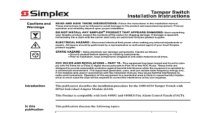
Introduction Instructions SPS 120 VAC mounts to expansion bays only RPS 120 VAC publication describes the installation procedure for the following 4100 Series System Power SPS and Remote Power Supplies RPS products are compatible with 4100U and 4100ES Fire Alarm Control Panels The SPS described in this document are not physically the same as the SPS SPS 220 230 240 VAC mounts to expansion bays only RPS 220 230 240 VAC Verify FACP System Programmer Executive and Slave Software compatibility installing or replacing system components Refer to the Technical Information and Downloads website for compatibility information in the CPU bay this Publication publication discusses the following topics Page and Warnings to the SPS and RPS the SPS and RPS Wiring Field Wiring Field Wiring SPS only Power Wiring Relay Wiring and relay connections can be made from the SPS the RPS supports relay connections only to the City and Relay Card Installation Instructions 574 839 to install a relay card to the or a city card to the SPS or RPS find out more about the CPU bay version of the SPS which operates in the same way as the bay version of the SPS but mounts differently refer to the 4100ES Fire Alarm System Guide 574 848 information on Expansion Power Supplies XPS refer to XPS and XNAC Installation 574 772 2005 2008 2009 2011 SimplexGrinnell LP All rights reserved and other information shown were current as of publication and are subject to change without notice and the Simplex logo are trademarks of Tyco International Ltd and its affiliates and are used under license K and Warnings yourself before opening or installing to installation keep components wrapped in anti static material at all times AND SAVE THESE INSTRUCTIONS Follow the instructions in this installation These instructions must be followed to avoid damage to this product and associated Product operation and reliability depend upon proper installation NOT INSTALL ANY SIMPLEX PRODUCT THAT APPEARS DAMAGED Upon your Simplex product inspect the contents of the carton for shipping damage If is apparent immediately file a claim with the carrier and notify an authorized Simplex supplier HAZARD Disconnect electrical field power when making any internal adjust or repairs All repairs should be performed by a representative or authorized agent of your Simplex product supplier HAZARD Static electricity can damage components Handle as follows RULES AND REGULATIONS PART 15 This equipment has been tested and found comply with the limits for a Class A digital device pursuant to Part 15 of the FCC Rules limits are designed to provide reasonable protection against harmful interference when the is operated in a commercial environment This equipment generates uses and can radio frequency energy and if not installed and used in accordance with the instruction may cause harmful interference to radio communications Operation of this equipment a residential area is likely to cause harmful interference in which case the user will be required correct the interference at his own expense REACCEPTANCE TEST AFTER SOFTWARE CHANGES To ensure proper operation this product must be tested in accordance with NFPA72 after any programming or change in site specific software Reacceptance testing is required after any change or deletion of system components or after any modification repair or adjustment to hardware or wiring components circuits system operations or software functions known to be affected by a must be 100 tested In addition to ensure that other operations are not inadvertently at least 10 of initiating devices that are not directly affected by the change up to a of 50 devices must also be tested and proper system operation verified to the SPS and RPS System Power Supply SPS and Remote Power Supply RPS are both intended to be placed in cabinets that require a 24 VDC signal power as well as battery charging capabilities The and RPS receive battery and AC power from the Power Distribution Module PDM SPS and RPS provide 24 VDC to three notification appliance circuits NACs can be Class B Y or Class A Style Z They are power limited according to UL 864 The NACs support TrueAlert and conventional reverse polarity operation SmartSync operation separate audible visible control on the same pair of wires NACs are monitored for short open circuits If a short circuit occurs the affected NAC is not energized During initialization system checks to see if any NACs are shorted together Notification Appliance Circuits on these modules can be used as Regulated 24 DC circuits or Application circuits When used as 24 VDC Regulated circuits only 4Amps of current is across the 3 circuits and any 24 VDC appliance may be attached When used as Special NACs the full 9Amps of current is available at the 3 circuits and only the compatible listed in Table 7 may be connected to these circuits The SPS RPS can synchronize appliances across all 3 circuits when those circuits are used as Special Applications power relay and relay module functions are also supported SPS and RPS perform standard fire alarm functions such as brownout detect battery transfer recharge and Earth fault detection The detection circuits signal an earth fault trouble when field wiring is connected to earth via a resistance of 10K ohms minimum the SPS provides an IDNet channel that supports initiating devices and some appliances such as the 4009 9201 and 9301 IDNet NAC Extender see Table 7 for devices The RPS does not provide an IDNet channel A relay option module may be to either the SPS or RPS mounts in the same location as the city module on the SPS The city module is not supported by RPS on next page to the SPS and RPS Continued figure below details the SPS The only difference in physical appearance between the SPS and RPS is that the SPS contains IDNet screw terminals Terminal Block TB2 Terminal Block TB1 SPS only Shield Port P2 Card Indication P3 Only Address SW1 Relay Block Power Block 1 Yellow 2 Yellow 3 Yellow 4 Yellow 5 Yellow 6 Yellow to of PDI P6 to Motherboard Connectors Fault Jumper P1 Card P7 Card Area card mounts to SPS Only Connector Board 1 The System Power Supply SPS SPS and RPS have the following LEDs when NAC 1 is in Alarm or Trouble when NAC 2 is in Alarm or Trouble when NAC 3 is in Alarm or Trouble to indicate a communications loss with the system CPU normally If this LED is blinking try re loading the software to FLASH IDNet status Slow blink Class A or open circuit trouble Fast blink Short circuit trouble ON steady No devices detected channel failure Normally OFF power supply status Single blink Positive Earth fault Double blink Negative Earth fault Triple blink Battery trouble Quadruple blink Charger trouble ON steady Overcurrent fault Normally OFF 7 Green Illuminates when the power supply is powered from the AC line OFF when the supply is de energized or when it is using battery backup power on next page to the SPS and RPS Continued table below summarizes the specifications for the SPS and RPS 1 Input and Output Specifications Input Specifications SPS RPS SPS RPS A Maximum VAC 60 Hz nominal A Maximum