Simplex Installation Instructions TrueAlert Power Supply

File Preview
Click below to download for free
Click below to download for free
File Data
| Name | simplex-installation-instructions-truealert-power-supply-2140967853.pdf |
|---|---|
| Type | |
| Size | 995.18 KB |
| Downloads |
Text Preview
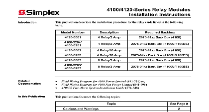
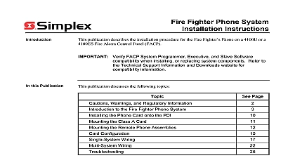
4100 5120 5121 5122 Power Supply Instructions publication provides an overview of the features specifications and capabilities of the power supplies TPS These supplies provide auxiliary power a battery charger and Signaling Line Circuits SLC Each of which provides control and power to the full range TrueAlert appliances TrueAlert power supplies are identical to each other with the following exceptions Domestic US version requires a 120 VAC power source Canadian version requires 120 VAC power source and provides battery cutout After installing a 4100 5121 refer to Low Battery Cutout Option in ES Panel Programmer Manual 574 849 for information on enabling this option International version uses a 220 240 VAC power source you are wiring Class A circuits you need to install a 4100 5124 Class A Adapter Card onto the Power Supply before installing the power supply Refer to Document 579 337 for information product is compatible with the 4100U and 4100ES Fire Alarm Control Panel FACP Verify FACP System Programmer Executive and Slave Software when installing or replacing system components to the Technical Support Information and Downloads website compatibility information this Publication publication discusses the following topics Page and Warnings to the TPS the TPS Distribution Module Battery Connections TrueAlert Devices Wiring Guidelines Class A Circuits Class B Circuits AUX Power 2001 2011 SimplexGrinnell LP All rights reserved and other information shown were current as of publication and are subject to change without notice and the Simplex logo are trademarks of Tyco International Ltd and its affiliates and are used under license K and Warnings AND SAVE THESE INSTRUCTIONS Follow the instructions in this installation manual instructions must be followed to avoid damage to this product and associated equipment operation and reliability depend upon proper installation NOT INSTALL ANY SIMPLEX PRODUCT THAT APPEARS DAMAGED Upon unpacking Simplex product inspect the contents of the carton for shipping damage If damage is immediately file a claim with the carrier and notify an authorized Simplex product HAZARD Disconnect electrical field power when making any internal adjustments repairs All repairs should be performed by a representative or authorized agent of your local product supplier HAZARD Static electricity can damage components Handle as follows yourself before opening or installing to installation keep components wrapped in anti static material at all times SAFETY HAZARD Under certain fiber optic application conditions the optical output of device may exceed eye safety limits Do not use magnification such as a microscope or other equipment when viewing the output of this device RULES AND REGULATIONS PART 15 This equipment has been tested and found comply with the limits for a Class A digital device pursuant to Part 15 of the FCC Rules These are designed to provide reasonable protection against harmful interference when the is operated in a commercial environment This equipment generates uses and can radio frequency energy and if not installed and used in accordance with the instruction may cause harmful interference to radio communications Operation of this equipment a residential area is likely to cause harmful interference in which case the user will be required correct the interference at his own expense REACCEPTANCE TEST AFTER SOFTWARE CHANGES To ensure proper operation this product must be tested in accordance with NFPA 72 after any programming or change in site specific software Reacceptance testing is required after any change or deletion of system components or after any modification repair or adjustment to hardware or wiring components circuits system operations or software functions known to be affected by a must be 100 tested In addition to ensure that other operations are not inadvertently at least 10 of initiating devices that are not directly affected by the change up to a of 50 devices must also be tested and proper system operation verified to the TPS features of the TrueAlert Power Supply are Three Signaling Line Circuits The TPS provides uninterruptible power and control to three channels of TrueAlert addressable notification appliances Each channel is referred to as Signaling Line Circuit SLC and is power limited power limited is defined in NFPA 70 Electric Code The SLCs can be either Class B Style 4 or Class A Style 6 Class A the installation of a Class A adapter board All SLCs are monitored for short and open AUX Power Provides up to 2 A of 24 VDC auxiliary power for use by the cards Battery Charger Charges up to 50 Ah ULC S527 or 110 Ah UL 864 Listing connected to the power supply The charger circuitry provides status monitoring of connection input power and Earth faults 1 2 3 Scroll Button 1 2 and 3 Corresponds an SLC Switches to SW8 to E Power Fault 1 Overview of TPS on next page to the TPS Continued Features Full TrueAlert Operation TrueAlert addressable notification appliances are individually and receive power supervision and control signals over the SLC Horns sound with high or low output using a temporal march time 60 or 120 beats per minute or pattern Horns are controlled separately from visible appliances installed on the same circuit Combination speaker strobe TrueAlert appliances receive audible control from audio circuit wiring Extensive Diagnostic Capabilities LEDs on the TPS flash codes that identify the nature of conditions The TPS also monitors for short and open circuits and positive and negative fault status Depleted Battery Cutout Canadian Version Only When AC Power fails the Depleted Cutout feature disconnects a battery from the panel when its voltage is approximately VDC Visual Synchronization A maximum of 46 MultiCandela addressable visuals may be per SLC All SLCs are synchronized across a TPS All TPSs are synchronized the FACP following table summarizes the AC Input DC Output and Battery Charger specifications of TPS 1 AC Input DC Output Battery Charger Specifications Power and SLC Voltage Voltage Voltage Current Input Specifications A Maximum VAC 60 Hz A Maximum VAC 50 or 60 Hz Output Specifications 19 VDC 32 VDC 2 VDC peak to peak full load 9A Charger Specifications VDC 500 mV 68 F 20 C temperature compensated mV deg C VDC V 3.3 A A For 6.2 Ah battery A Default for 18 50 Ah battery Canada 18 110 Ah battery States on next page to the TPS Continued Current 2 lists the battery standby requirements for the TPS The voltage is 24 VDC which is the rated voltage for lead acid type batteries 2 Battery Standby no alarms SLCs normal 3 SLCs ON A option Standby or Alarm mA mA mA TPS operates normally within the following temperature range 32 F 0 C and 120 F 49 C 90 32 C degrees at 93 Relative Humidity non condensing Add auxiliary and card power currents to standby current For each TrueAlert appliance add mA standby current The maximum auxiliary current is 2A The maximum card power is 2A card power and auxiliary currents from 9A total power supply capacity power supply alarm capacity is 9A