Simplex MAPNET II, 4 to 20mA ZAM Installation Instructions

File Preview
Click below to download for free
Click below to download for free
File Data
| Name | simplex-mapnet-ii-4-to-20ma-zam-installation-instructions-1093672845.pdf |
|---|---|
| Type | |
| Size | 675.77 KB |
| Downloads |
Text Preview
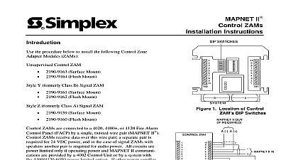
Cautions and II mA Monitor ZAM Instructions NOT INSTALL ANY SIMPLEX PRODUCT THAT APPEARS DAMAGED Upon your Simplex product inspect the contents of the carton for shipping damage If is apparent immediately file a claim with the carrier and notify Simplex HAZARD Disconnect electrical power when making any internal adjustments or Servicing should be performed by qualified Simplex Representatives HAZARD Static electricity can damage components Therefore handle as follows Ground yourself before opening or installing components Keep uninstalled component wrapped in anti static material at all times document provides descriptions and recommendations for connecting the Simplex 20 mA ZAM to a third party sensor The 20 mA Monitor ZAM or Analog Monitor ZAM AMZ a four wire MAPNET II peripheral that provides a complete electrical interface to compatible that provide a linearized 4 20mA loop output to transmit signal information The interface includes 24 VDC nominal power an input for signaling a sensor trouble condition and an for driving an auxiliary alarm LED sensor mA loop sensor output Surface mount AMZ LED VDC power Area contacts control of local functions II 35 2 MONITOR STAGE 1 ALARM MAPNET II fire panel showing typical message 1 20 mA Monitor ZAM Connections on next page the Simplex logo and MAPNET are registered trademarks of Simplex Time Recorder Co II Communication Net is protected by U S Patent No 4,796,025 2000 Simplex Time Recorder Co Westminster MA 01441 0001 USA All Rights Reserved specifications and other information shown were current as of publication and are subject to change without notice D 20 mA Monitor ZAM Continued AMZ is used in the monitoring of toxic and combustible gas levels received from a compatible device not supplied and then reporting the selected levels back to the fire alarm panel via MAPNET II channel All circuits are power limited only if operating power and MAPNET II are provided by a 4020 Control Unit or by one of the Model 4100 power limited supplies If other power supplies or systems are used circuits are not power limited sure you have the appropriate software revisions before installing an AMZ Installing an in the 4020 or 4100 Fire Alarm Panel requires the following software revisions Revision 8.01 of the Programmer Unit and Master Controller Revision 6.01 of the MAPNET II Card Software Revision 2.04 4020 Standard Slave or Revision 5.01 4020 U P S Standard Slave Fire Alarm Panel only required if AMZ is added to the standard slave II channel 2 below is an illustration of the 20 mA Monitor ZAM along with its outputs DIP and Walk Test pushbutton DIP SWITCHES TEST FROM POWER SUPPLY 0V II RETURN RETURN POWER SIGNAL TO IN FOR TO POINTS 2 The 20 mA Monitor ZAM installation consists of the following steps Setting the AMZ address and labeling the AMZ See Figure 1 for the location of the AMZ switch Connecting MAPNET II wiring for communication sensors and system power Mounting the AMZ to the panel 1 Setting the AMZ Address Setting for 4020 or 4100 AMZ has a unique address This address is associated with an SMPL custom label that its physical location within the building The AMZ address and location must match address listed in the specification sheets of the 4020 Programmer Report or the 4100 Report the 4020 or 4100 Programmer Report find the entry for the AMZ you are about to install DEVICE ADDRESS with an prefix and CUSTOM LABEL are located in the SYSTEM SUMMARY the example circled in Figure 3 The circled address is M1 7 for the 4020 or 4100 system is addressable channel 1 and 7 is the device address on the channel For an AMZ with address Address 7 circled in Figure 3 must be set on the AMZ DIP switch 3 System Point Summary with MAPNET II Addresses on next page 1 Setting the AMZ Address Continued Setting for 4020 or 4100 IS SHOWN SET AT ADDRESS 7 ON OFF THRU 4 SWITCHES 5 THRU 8 1000 0100 1100 0010 1010 0110 1110 116 117 118 119 120 121 122 123 124 125 126 127 4 MAPNET II Address Chart the example on the previous page as a guideline set the AMZ address using Figure 4 See 1 for the location of the AMZ DIP switch For 4020 and 4100 systems is switch while is switch you are done mark an address label with the appropriate address for your AMZ by shading label box for each AMZ DIP switch in the ON position Apply the label to the AMZ near the switch Double check the location of the AMZ and its address before making electrical 2 Wiring II Power AMZ requires connections for MAPNET II communications power from the host source and signaling Each type of wiring is described below AMZ MAPNET II interface is electrically isolated from the AMZ power and sensor interface This allows a relatively distant host panel to control the AMZ and monitor the sensor via II while a relatively close power source can supply the AMZ sensor combination II and power connections are run separately their return lines must not be the AMZ to the MAPNET II wire pair and power supply using Figure 1 as a reference to the appropriate 4020 or 4100 panel cabinet drawings for MAPNET II connections remote mount version of the AMZ 4190 9050 or 4190 9051 provides 18 AWG flying leads T tapping into the MAPNET II wiring via wire nuts Wires are present for the MAPNET MAPNET signals the MAPNET shield wiring does not connect to the AMZ conductors panel mount version of the AMZ 4100 0540 or 4120 0540 provides terminal blocks for connections of MAPNET and MAPNET shield wiring Each terminal block two 18 AWG conductors to the wiring diagrams in MAPNET II devices 841 804 for actual conductor connections general MAPNET II wiring guidelines power connections for the AMZ to the host power supply are flying lead connections in the version and terminal block connections in the panel mount version sensor specifications require as much as a 350 mA input at the low end of their supply range If long wire runs from power source to sensor are required installations with power loads that are served by a single fire alarm power source must be carefully planned attention to AMZ placement as well as to wiring lengths between the power source and the general higher current devices 3 or 4 wire require the clustering of AMZs around the power in order to minimize the lengths of the wire runs allowed from the source to each sensor no condition should the wiring distance from the power source to the furthest sensor 1 km 3270 feet allow for a 0.8 V drop at the AMZ when considering sensor compatibility and when the power runs from power source to sensor on next page 2 Wiring Continued Wiring wiring between the AMZ and the sensor not supplied is twisted pair Refer to the sensor installation manual for shielding requirements If a shield is used connect the shield to ground at only one end of the