Simplex MAPNET II Addressable Modules 2190-9172, -9172A Supervised IAMs Installation Instructions

File Preview
Click below to download for free
Click below to download for free
File Data
| Name | simplex-mapnet-ii-addressable-modules-2190-9172-9172a-supervised-iams-installation-instructions-5704296381.pdf |
|---|---|
| Type | |
| Size | 923.56 KB |
| Downloads |
Text Preview
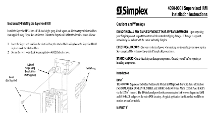
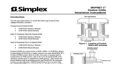
SSimplex WAddressable Modules 9172A Supervised IAMs Instructions 2190 9172 or 2190 9172A Supervised Transponder 4020 4100 or 4120 System by a single wire pair MAPNET power and data over this pair no additional wiring is required unless Style 6 operation a 2120 Multiplex MAPNET is connected The IAM receives used 2190 9172 or 2190 9172A is designed monitor normally open N O alarm contacts installation consists of Setting the IAM address and labeling the IAM Making electrical connections Mechanically the IAM IAM A Setting the IAM Address and Labeling the IAM IAM has a unique address This address a building The IAM address and location must match up with the address the 2120 Job Configuration Report File 4020 Programmer Report or 4100 Programmer Report associated with a custom label which identifies physical location in the specification sheets Setting for the 2120 CDT System Using the 2120 Job Configuration Report File find the entry for the IAM you are about to install The CUSTOM column provides location while the DEVICE ADDRESS column provides set the IAM address See Figure 1 for location of switch setting data z z Using the switch setting data for the IAM you Use a small screwdriver or pen to set the switches the switch setting data in the DEVICE ADDRESS column is switch while is switch DIP Switch 8 is used for alarm latch while Double check location of the IAM and its address before proceeding Part B TO N O ALARM WIRE TO MAPNET AND LEADS USING WIRE NUTS MODULE of IAM DIP Switches and Unit Interconnections 1 following an digit Product ID number denotes ULC listed product Communication Net is protected by U S Patent No 4,796,025 1995 Simplex Time Recorder Co Gardner MA 01441 0001 1995 Simplex specifications Time Equipment Co Ltd Mississauga Ontario L4V 1 H3 Canada other were current as of publication are subject change without notice 574 675 6 95 Setting for the 4020,4100 or 4120 System Using the Programmer Report for the 4020 4100 or 4120 find the entry for the IAM you are about to install DEVICE ADDRESS and CUSTOM LABEL are located in the SYSTEM POINT SUMMARY under example Address Ml 7 for the 4100 or 4120 system is circled in Figure 2 Ml is the addressable channel 7 is the device address on the channel For an IAM with Address Ml 7 Address 7 circled in Table 1 must set on the IAM DIP switches an IAM with Address Ml 117 must have Address 117 set on its DIP Using the example given in Step 1 as a guideline set the IAM address using Table 1 See Figure 1 for location switches Use a small screwdriver or pen to set the switches Note 4920 isswiteh while is switch Mark an address with the appropriate address for your IAM by shading a corresponding DIP switch in the ON position apply the label to the IAM near the IAM DIP switches marked Address 7 with Alarm Latch is shown box for each Figure 3 Double check location of the IAM and its address before proceeding Part B Point zone name System POINT SUMMARY Name CARD 1 POINT 101 CARD 1 POINT 102 CARD 1 POINT 103 CARD 1 POINT 104 LAB BLDG 21 FLOOR EAST WING ROOM 18 FLOOR WEST WING ROOM 12 EAST WING ROOM 3 109 ADDRESS 14 JUN 95 4 SUMMARY PEiL Point zone name or 4120 System POINT SUMMARY Name FLOOR MICROWAVE ROOM FLOOR DINING ROOM FLOOR LOBBY FLOOR MECHANICAL ROOM 2 FLOOR LOADING DOCK FLR MECH RM 1 FLR MEXH RM 1 ADDRESS 14 JUN 95 2 SUMMARY Point Summaries with MAPNET II 2 ON OFF II Ad Ire Label 4020,4100 or 4120 Only 3 1 II Address Label 4020,4100 or 4120 Only 8 CLEARS ON RESET 1 3 4 6 8 8 8 10 12