Simplex MAPNET II Communicating Devices, Model 2190-9173 2-Point I O Module

File Preview
Click below to download for free
Click below to download for free
File Data
| Name | simplex-mapnet-ii-communicating-devices-model-2190-9173-2-point-i-o-module-0735148296.pdf |
|---|---|
| Type | |
| Size | 701.10 KB |
| Downloads |
Text Preview
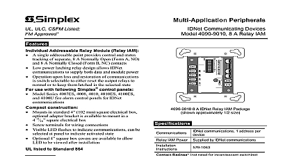
ULC CSFM Listed FM Approved NYC Acceptance II Communicating Devices Model 2190 9173 2 Point I O Module Supervised Input and Control Relay Output II addressable module providing a input and a control relay output in one package For use with Simplex fire alarm control panels that MAPNET II addressable communications Module uses two sequential addressable points with designation requiring only one address selection Low power latching relay design allows MAPNET II to supply both data and module Relay is set to OFF on initial power up and upon loss of communications UL listed to Standard 864 input point Monitors status of normally open dry contacts for normal open and contact closure Operation reports to the MAPNET II channel as a supervised Individual Addressable IAM control relay Power limited rating 2 A 30 VDC resistive A 30 VDC inductive Non Power limited rating 1 2 A 120 VAC 1 4 A 120 VAC inductive Operation reports to the MAPNET II channel as a Zone Adapter Module ZAM sealed construction Enclosed design minimizes dust infiltration Mounts in standard 4 102 mm square electrical box adapter bracket is available to mount in a 4 11 electrical box I O Module The 2190 9173 2 Point I O allows a Simplex MAPNET II communication to monitor an input contact closure and control an relay from a single compact module Module is supplied from the MAPNET II communications eliminating the need for separate power wiring Operation The input and output are and operation is controlled by the host panel selection Points may be directly associated each other such as monitoring the status of the function by the contacts or may be programmed for operation This product has been approved by the California State Fire Marshal CSFM pursuant to 13144.1 of the California Health and Safety Code See CSFM Listing for allowable values and or conditions concerning material presented in this Accepted for use City of New York Department of Buildings MEA35 93E listings may be applicable contact your local Simplex product supplier for the status Listings and approvals under Simplex Time Recorder Co are the property of Fire Protection Products 2 Point I O Module approximately 1 2 size Applications Efficient Package For smoke control applications this provides an efficient package for fan damper with feedback The monitor point connects to a position indicator switch allowing the host panel to the fan damper status with respect to the requested control operation Applications The monitor and control points be applied for a variety of associated or independent Flexible programming abilities at the host can provide the association logic required for a variety of fire or utility operations Selection 2 Point I O Module Adapter plate to fit 4 11 119 mm square box Power Information Refer to diagram on page 2 by MAPNET II two addresses required per module Addresses Connections Screw terminals for in out wiring address setting selects an even address for the input point and next sequential odd number is automatically assigned to control point to 12 AWG wire 0.82 to 3.31 mm2 H x 4 W x 1 D mm x 105 mm x 35 mm Material Black thermoplastic Plate Range metal galvanized F to 120 F 0 C to 49 C for indoor operation to 93 RH at 100 F 38 C 11 2013 Wiring Reference Distance to Monitored Contacts For internal wiring run no overvoltage protector 500 ft 152m For wiring external to building using a 2081 9044 overvoltage protector 400 ft 122 m overvoltage use when locate where leaves building separately Limited Contact Ratings A 30 VDC resistive transient loads A 30 VDC for inductive loads p f max Limited Contact A 120 VAC resistive suppressed loads A 120 VAC for inductive 0.35 p f max k W 4081 9004 733 886 II host panel II Wiring Distances Up to 2500 ft 762 m from host control panel Up to 10,000 ft 3048 m total wiring distance including T taps Refer to Installation Instructions 574 995 and Field Wiring Diagrams and 841 996 for detailed installation information Mounting Information SIMPLEX and the product names listed in this material are marks and or registered marks Unauthorized use is strictly prohibited Fire Protection Products Westminster MA 01441 0001 USA 11 2013 2013 Tyco Fire Protection Products All rights reserved All specifications and other information shown were current as of document revision date and are subject to change without notice


