Simplex MAPNET II Transceiver - Installation Instructions
File Preview
Click below to download for free
Click below to download for free
File Data
| Name | simplex-mapnet-ii-transceiver-installation-instructions-4907318526.pdf |
|---|---|
| Type | |
| Size | 1.78 MB |
| Downloads |
Text Preview
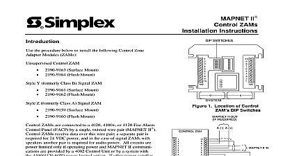
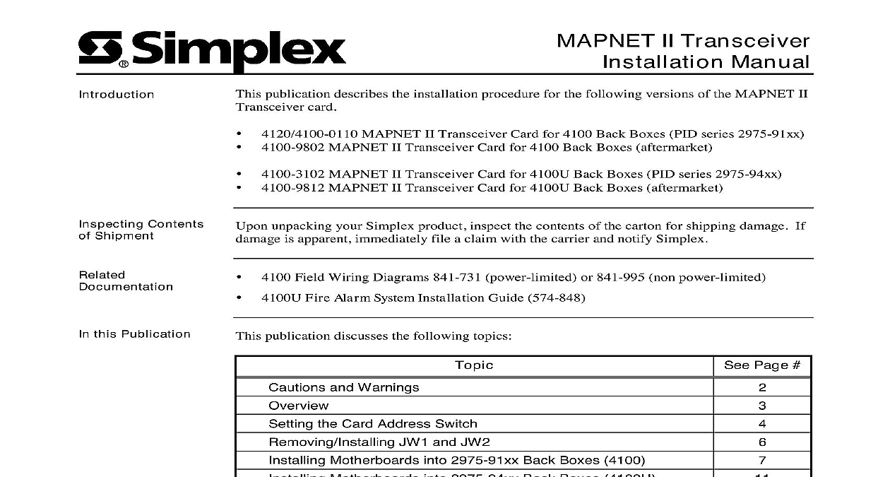
MAPNET II Transceiver Manual publication describes the installation procedure for the following versions of the MAPNET II card MAPNET II Transceiver Card for 4100 Back Boxes PID series 2975 91xx MAPNET II Transceiver Card for 4100 Back Boxes aftermarket MAPNET II Transceiver Card for 4100U Back Boxes PID series 2975 94xx MAPNET II Transceiver Card for 4100U Back Boxes aftermarket unpacking your Simplex product inspect the contents of the carton for shipping damage If is apparent immediately file a claim with the carrier and notify Simplex Field Wiring Diagrams 841 731 power limited or 841 995 non power limited Fire Alarm System Installation Guide 574 848 Contents Shipment this Publication publication discusses the following topics Page and Warnings the Card Address Switch JW1 and JW2 Motherboards into 2975 91xx Back Boxes 4100 Motherboards into 2975 94xx Back Boxes 4100U the Daughter Card the MAPNET Channel and Power Connections 2001 Simplex Time Recorder Co Westminster MA 01441 0001 USA specifications and other information shown were current as of publication and are subject to change without notice A and Warnings AND SAVE THESE INSTRUCTIONS Follow the instructions in this installation These instructions must be followed to avoid damage to this product and associated Product operation and reliability depends upon proper installation NOT INSTALL ANY SIMPLEX PRODUCT THAT APPEARS DAMAGED Upon your Simplex product inspect the contents of the carton for shipping damage If is apparent immediately file a claim with the carrier and notify Simplex HAZARD Disconnect electrical field power when making any internal or repairs Servicing should be performed by qualified Simplex Representatives HAZARD Static electricity can damage components Therefore handle as follows Ground yourself before opening or installing components use the 553 484 Static Control Prior to installation keep components wrapped in anti static material at all times SAFETY HAZARD Under certain fiber optic application conditions the optical output of device may exceed eye safety limits Do not use magnification such as a microscope or other equipment when viewing the output of this device FREQUENCY ENERGY This equipment generates uses and can radiate radio energy and if not installed and used in accordance with the instruction manual may interference to radio communications It has been tested and found to comply with the for a Class A computing device pursuant to Subpart J of Part 15 of FCC Rules which are to provide reasonable protection against such interference when operated in a environment Operation of this equipment in a residential area may cause interference which case the user at his own expense will be required to take whatever measures may be to correct the interference REACCEPTANCE TEST AFTER SOFTWARE CHANGES To ensure proper operation this product must be tested in accordance with NFPA72 1996 Chapter 7 after programming operation or change in site specific software Reacceptance testing is required any change addition or deletion of system components or after any modification repair or to system hardware or wiring components circuits system operations or software functions known to be affected by a must be 100 tested In addition to ensure that other operations are not inadvertently at least 10 of initiating devices that are not directly affected by the change up to a of 50 devices must also be tested and proper system operation verified Information MAPNET Transceiver Card consists of two cards a motherboard that mounts into either a bay or an expansion bay and a daughter card that mounts into the motherboard General of the MAPNET Transceiver Card include Connects up to 127 addressable MAPNET devices to the 4100 Supports either Class A or Class B wiring MAPNET Transceiver Motherboard provides isolated 36 VDC power for the MAPNET This power has the following specifications Voltage 36 VDC 5 7.5 up to 500 mA Ripple 100 mV RMS F to 120 F Relative Humidity 86 F environment in which the transceiver card is mounted must be within the following range the Card Address Switch SW1 on the MAPNET Transceiver Daughter Card is a bank of eight dip switches From to right see figure below these switches are designated as SW1 1 through SW1 8 The of these switches is as follows SW 1 1 This switch sets the baud rate for the serial communication line running between daughter card and the 4100 CPU Set this switch to ON SW1 2 through SW1 8 These switches set the card address within the 4100 FACP switches must be set to the value assigned to the card by the 4100 Programmer Refer Table 1 for a complete list of the switch settings for all of the possible card addresses a switch to the down position to turn it ON or to the up position to turn it OFF Switches 1 2 through 1 8 the Card Address Figure an Address of 3 Refer Table 1 for switch settings Rate SW 1 1 Be Set to 1 DIP Switch SW1 on next page the Card Address Switch Continued continued 1 4100 Daughter Card Addresses 1 2 1 3 1 4 1 5 1 6 1 7 1 8 1 2 1 3 1 4 1 5 1 6 1 7 1 8