Simplex Model 2081-9028 Isolated Loop Circuit Protector Installation Instructions

File Preview
Click below to download for free
Click below to download for free
File Data
| Name | simplex-model-2081-9028-isolated-loop-circuit-protector-installation-instructions-7519830642.pdf |
|---|---|
| Type | |
| Size | 669.41 KB |
| Downloads |
Text Preview
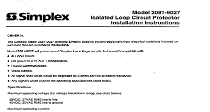
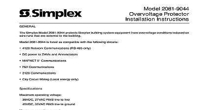
Overview Specifications signals must not exceed the following operating specifications 2081 9028 Loop Circuit Protector Instructions 2081 9028 Isolated Loop Circuit Protectors ILCP protect Simplex systems equipment from electrical transients such as those caused by strikes or disturbances on high voltage power lines induced on circuit external to the building 2081 9028 circuit protectors can be used to protect most Simplex low circuits such as DC Notification Appliance Circuits NACs and circuit NACs 25 VRMS but are not compatible with the following AC input power RS 232 communication Video signals 1 Operating Specifications Rating Rating Rating Current Rating Resistance Inductance Capacitance Time Current and Current VDC 28 VAC RMS line to line VDC 28 VAC RMS line to ground VDC 33 VAC RMS Amps than 0.1 Ohms per line per line Nanosecond 10 9 line to line and A 8x20 pulse A 10x50 pulse this Publication publication discusses the following topics the Isolated Loop Circuit Protector Page 2000 Simplex Time Recorder Co Westminster MA 01441 0001 USA specifications and other information shown were current as of publication and are subject to change without notice A the Isolated Loop Circuit Protector Guidelines the following guidelines before installing the 2081 9028 UL 497B Listing Requirements The external wiring must be confined a one block area containing the building of origin The wiring must also installed in such a manner that there is no possibility of accidental by failure of supports or insulation with electric light or power operating at over 300 V peak to ground Location For optimal protection install the 2081 9028 apart from the equipment and as close as practical to the point where the circuit or enters the building ILCPs must be installed in dedicated metallic boxes Separate Conduit Protected and unprotected equipment must not share same conduit Wire Type Fire alarm system wiring that is external to the building and by the use of 2081 9028 ILCPs must use twisted shielded pairs must be properly grounded Wiring Distance Wiring is limited to one contiguous property The total wire length is determined by the allowable limit of the circuit example a MAPNET circuit is limited to 2500 ft minus losses for suppressors and some signal circuits NACs could be as low as a hundred feet depending on the type of devices connected to the No circuit can exceed 3270 feet 1 km Underground Wiring Wiring must be in a wiring trough that is separate commercial distribution wiring Overhead Wiring Keep the following in mind with regard to overhead Wiring must be run on poles separate from those supporting any power wiring Wiring shall be run in parallel with the commercial power distribution and be separated by a minimum distance of either 100 ft 30 m the maximum span between any two adjacent poles of either the circuit or the commercial power distribution circuit Ground The grounding connector shall be 12 AWG with a maximum of 28 feet 8.5 m Ground wire must be run in as straight a line as and must be connected to the building grounding electrode system Article 800 40 of NFPA 70 the National Electric Code Procedure Mount the 2081 9028 in a steel box At least 2 inches 5.08 cm must the from the conduit Permissible box sizes are square preferred square x 2 1 8 in deep 11 16 square on next page the Isolated Loop Circuit Protector Continued Procedure Cut the 2081 9028 green lead as short as possible and tie it to the box with a standard grounding screw Bond the box containing the 2081 9028 to the building grounding electrode of the building containing the equipment to be protected these guidelines when bonding the 2081 9028 to the grounding Use 12 AWG 3.309 mm or larger solid copper wire Ground wire must not exceed 28 feet 8.6m Bends in ground wire of less than a 2 inch 5.08 cm radius are not enclosed in metal conduit the ground wire must be bonded to the at both ends Wire the 2081 9028 as described below Use Figure 1 as a Reference Connect the 2081 9028 brown and violet leads to the lines coming the protected equipment Connect the 2081 9028 orange and yellow leads to the lines going out the building Connect one of the 2081 9028 gray leads to one of the cable shields connect the remaining gray lead to the other shield At the 2081 9028 dress the input and output cables as far apart as possible distance between input and output cables can be no less than 2 inches cm At the signal source connect the cable shield to the cabinet ground screw sources can be either of the following Power supply for power circuits Transponder or FACP for Notification Appliance Circuits on next page the Isolated Loop Circuit Protector Continued Procedure A B AWG min ILCP circuit A B the next AWG min ft max Square box 2 1 8 deep equivalent by others 1 Wiring Diagram A