Simplex Multi-Application Peripherals, Audible Visible Appliances, Electronic Horn with Strobe Selectable as Free-Run or Synchronized
File Preview
Click below to download for free
Click below to download for free
File Data
| Name | simplex-multi-application-peripherals-audible-visible-appliances-electronic-horn-with-strobe-selectable-as-free-run-or-synchronized-4259761083.pdf |
|---|---|
| Type | |
| Size | 661.37 KB |
| Downloads |
Text Preview
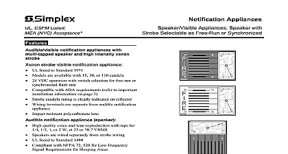
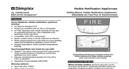
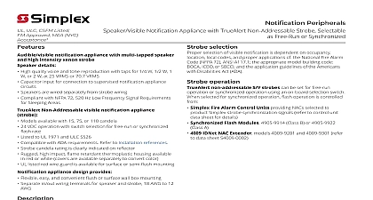
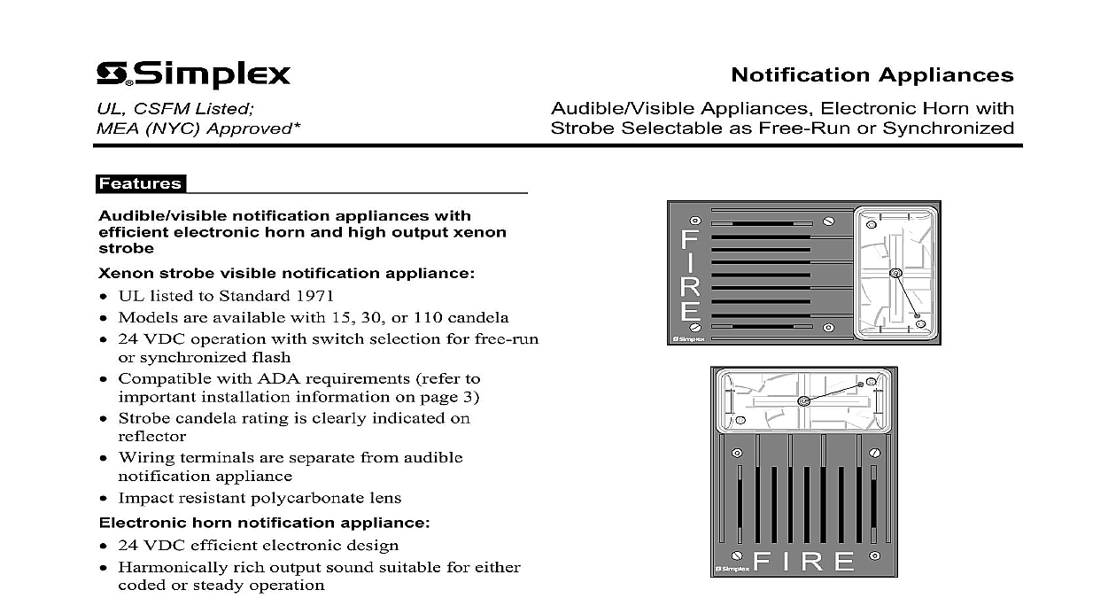
CSFM Listed NYC Approved Appliances Appliances Electronic Horn with Selectable as Free Run or Synchronized notification appliances with electronic horn and high output xenon strobe visible notification appliance UL listed to Standard 1971 Models are available with 15 30 or 110 candela 24 VDC operation with switch selection for free run synchronized flash Compatible with ADA requirements refer to installation information on page 3 Strobe candela rating is clearly indicated on Wiring terminals are separate from audible appliance Impact resistant polycarbonate lens horn notification appliance 24 VDC efficient electronic design Harmonically rich output sound suitable for either or steady operation Diode polarized input for connection to reverse supervised notification appliance circuit UL listed to Standard 464 Options Red with white FIRE lettering for horizontal or mounting A V notification appliances combine high intensity strobe with a low current electronic horn horn output provides a steady harmonically rich that can be easily coded by the controlling appliance circuit NAC combination horn and strobe can be wired to the NAC or for applications requiring separate audible visible circuits jumpers located at the wiring can be easily removed I R E Notification Appliances with Electronic are Available for Horizontal or Vertical Mounting Synchronization strobes of these S V notification appliances can be set free run operation or synchronized operation using an selection switch When selected for synchronized flash operation is controlled from Synchronized Flash Modules 4905 9914 Class B 4905 9922 Class A 4007ES Hybrid 4008 4010 4010ES 4100ES 4100U Fire Alarm Control Panels refer to product data sheets for details IDNet NAC Extender models 4009 9201 and refer to data sheet S4009 0002 Refer to page 2 for guard listing These A V products have been approved by the State Fire Marshal CSFM pursuant to Section 13144.1 of the California and Safety Code See CSFM Listing 7125 0026 249 for allowable values and or concerning material presented in this document Accepted for use City of York Department of Buildings MEA35 93E This product was not ULC listed or FM as of document revision date Additional listings may be applicable contact local Simplex product supplier for the latest status Listings and approvals under Time Recorder Co are the property of Tyco Fire Protection Products Refer to data sheet S4905 0003 for additional information on Synchronized Flash 11 2014 Application Reference selection of visible notification is dependent on location local codes and proper application the National Fire Alarm Code NFPA 72 A117.1 the appropriate model building code ICBO or SBCCI and the application guidelines the Americans with Disabilities Act ADA Product Selection Accessories Output Candela Mounting Style Wall Mount Wall Mount Boxes see illustrations on page 4 Surface Mount Box Box for vertical or horizontal mount requires adapter plate 4905 9903 box may be available for retrofit applications x 7 7 8 x 2 3 4 Deep mm x 200 mm x 70 mm x 6 5 8 x 2 3 4 mm x 168 x 70 mm x 8 5 16 mm x 211 mm x 4 7 8 mm x 124 mm x 6 7 8 x 1 1 2 deep 121 mm x 175 mm x 38 mm Plates and Box Extension Rings see illustrations on pages 3 and 4 Adapter Plate required to mount on 2975 9145 box Plate zinc plated required for surface mounted three gang box no V5744 3 or equal and for double gang boxes typically for applications For surface mounted 4 square electrical boxes either Adapter Plate or an Adapter Ring Box Extensions is required see below Adapter Ring Box Extension use to mount onto and cover surface mount electrical box Flash Modules Refer to data sheet S4905 0003 for additional details Flash Module B operation Flash Module A operation Guard see illustrations on page 4 encapsulated with in out 18 AWG mm2 wire leads rated for 2 A requires 5 mA for power W x 2 7 16 L x 13 16 H mm x 62 mm x 20 mm Wire Guard for semi flush mounting requires mounting plate for use with 4905 9923 or 2975 9145 boxes Adapter Plate required to mount wire guard to 4905 9924 or 2975 9145 boxes Reference Age Model Age Model x 6 1 8 x 3 mm x 156 mm x 76 mm x 7 mm x 178 mm 11 2014 A V Accessories Specifications Voltage Range Rate and Synchronized NAC Loading RMS Current Rating per Strobe see Note 2 below Listed Range Regulated 24 VDC see Note 1 below Hz with up to 35 synchronized strobes maximum per NAC cd mA mA mA cd mA mA mA cd mA mA mA VDC VDC mA 16 VDC Listed Range 16 VDC to 33 VDC see Note 3 below Currents other voltages Specifications see Note 3 Voltage Range Current Output 10 ft per UL Standard 464 room testing Output Specifications Dimensions with lens into Box Temperature Range Range 24 VDC refers to the voltage range of 16 to 33 VDC per UL Standard 1971 Signaling Devices for the Hearing x 6 7 8 x 2 5 8 D 121 mm x 175 mm x 67 mm 17 mm for in out wiring 18 to 12 AWG 0.82 to 3.31 mm2 separable if required to 120 F 0 to 49 C to 95 Non condensing at 86 F 30 C Hz to 3700 Hz sweep modulated at 120 Hz rate dBA 33 VDC dBA 16 VDC mA 33 VDC This voltage range is the absolute operating range Operation outside of this range may cause permanent damage to appliance Please note that 16 VDC is the lowest operating voltage that is allowed at the last appliance on the NAC under case conditions The strobe of this A V is field selectable for free run or synchronized operation The maximum RMS current listed is the device nameplate rating Strobe designs are constant wattage and the maximum RMS rating occurs at the lowest allowable operating voltage RMS is root mean square and refers to the effective value of a current waveform Horns may be connected to either the same circuit as the strobe or may be separated for connection to separate NACs that individual control A V with Electronic Horn Semi Flush Mounting box square 1 1 2 deep box 191 or equal by others box 4905 9939 Adapter Plate INSTALLATION HEIGHT REFERENCE 72 requires that the entire be not less than 80 2.03 and not greater than 96 m above the finished floor outlet box 2 1 2 RACO 518 or typical for retrofit by others 4905 9939 Adapter 11 2014 A V with Electronic Horn Surface Mounting Box Adapter Plate Box 4 square box on wall box Ring Mount Mount Mount using 2975 9145 Box assembly Square box mounted View View Mount to 4 Box with Adapter Ring Extension or 4905 9924 Mount Box adapter plate required