Simplex MX Technology Addressable Devices; Addressable Manual Stations, Single and Dual Action

File Preview
Click below to download for free
Click below to download for free
File Data
| Name | simplex-mx-technology-addressable-devices-addressable-manual-stations-single-and-dual-action-9438075612.pdf |
|---|---|
| Type | |
| Size | 646.51 KB |
| Downloads |
Text Preview
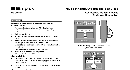
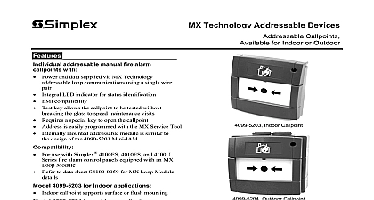
Listed Technology Addressable Devices Manual Stations and Dual Action addressable manual fire alarm with Power and data supplied via MX Technology loop communications using a single wire EMI compatibility Address is easily programmed with the MX Service mounted addressable module is similar to design of the 4090 5201 Mini IAM Available as single action or double action breakglass Pull lever that protrudes when alarmed Break rod supplied use is optional UL listed to Standard 38 For use with Simplex 4100ES 4010ES and 4100U fire alarm control panels equipped with an MX Module Refer to data sheet S4100 0059 for MX Loop Module construction Electronics module enclosure minimizes dust Allows mounting in standard electrical boxes Screw terminals for wiring connections resistant reset key lock keyed same as fire alarm cabinets mounting options Surface or semi flush with standard boxes or matching boxes Flush mount adapter kit Adapters are available for retrofitting to commonly existing boxes addressable stations contain an integral addressable that constantly monitors status and communicates an MX Loop Module located in the host fire alarm panel Listings and approvals under Simplex Time Recorder Co are the property of Tyco Fire Products DOWN Single Action Manual Station and side view GLASS Double Action Manual Station of the 4099 5201 single action manual requires a firm downward pull to activate the switch Completing the action breaks an internal break rod visible below the pull lever use is The use of a break rod can be a deterrent to without interfering with the minimum pull needed for easy activation The pull lever into the alarm position and remains extended out the housing to provide a visible indication Action Stations Breakglass require the to strike the front mounted hammer to break the and expose the recessed pull lever The pull lever operates as a single action station reset requires the use of a key to reset the station lever and deactivate the alarm switch If break rod is used it must be replaced testing is performed by physical activation of pull lever Electrical testing can be also performed by the station housing to activate the alarm switch 11 2011 MX Technology Addressable Manual Station Product Selection Manual Stations Red Housing with White Letters and White Pull Lever action operation Double action Breakglass operation mount steel box red Cast aluminum surface mount box red Replacement breakglass Replacement break rod trim plate for double gang switch box red trim plate for Wiremold box V5744 2 red mount adapter kit black mount adapter kit beige cover kit for field installation on 4099 9001 to page 3 for dimensions to page 4 for details Specifications and Communications Means Connections Listed Temperature Range Range Color Lever Color Dimensions Instructions Loop 1 address per manual station mA standby and alarm with MX Service Tool blocks for wire size 20 to 14 AWG 0.5 to 2.5 mm2 to 120 F 0 to 49 C intended for indoor operation to 93 RH at 100 F 38 F with white raised lettering and pull lever are Lexan polycarbonate or equal with red raised lettering H x 3 W x 1 D 127 mm x 95 mm x 25 mm Addressable Manual Station Semi Flush Mounting DOWN 11 2011 Single Gang Box 35 mm depth use box with only two tabs supplied separately mm x 72 mm x 35 mm min x 2 7 8 x 1 3 8 Box separately H x 4 W x 2 3 16 D mm x 102 mm x 56 mm Addressable Manual Stations Surface Mounting Mounting For mounting of these manual stations the electrical boxes are in the illustration to the Mounting Refer to page 4 for box mounting located and bottom Cast Box H x 3 7 8 W x 2 3 16 D mm x 98 mm x 56 mm separately DOWN mm for 3 4 threaded located top and bottom 25.4 mm 95 mm Series Addressable Manual Station Surface Mount Side View with Internal Detail View width mm 2975 9178 box for reference wiring for reference mm cover hinges open installation access wiring mm Application Reference to NFPA 72 the National Fire and Signaling Code and all local codes for complete for manual stations The summarizes the basic Stations shall be located in the path of exit and distributed the protected area such that they unobstructed and readily Mounting shall be with the part not less than 3 ft m and not more than 4 ft m above floor level At least one station shall be on each floor Additional shall be provided to obtain travel distance not more than ft 61 m to the nearest station any point in the building When manual station coverage limited in any way stations should be 11 2011 Addressable Manual Station Additional Mounting Information retrofit and new installations additional mounting boxes and the required plates are shown in the illustration the right Surface trim Wiremold box H x 5 W mm x 127 mm box V5744 2 by gang switch box each H x 2 W x 2 3 4 D mm x 51 mm x 70 mm by others Addressable Manual Station Flush Mounting Information Semi flush trim for 2 gang box 6 H x 4 1 2 W mm x 114 mm mount adapter kit Black Beige must be recessed into wall to 1 1 8 25.4 mm to 29 mm mm cutout must be a of 6 H by 5 W 152 mm by 127 mm 119 mm box 2 1 8 mm minimum by others 121 mm 171 mm View SIMPLEX and the product names listed in this material are marks and or registered marks Unauthorized use is strictly prohibited NFPA 72 and National Fire Alarm are trademarks of the National Fire Protection Association NFPA Lexan is a trademark of the General Electric Co Wiremold is a trademark of the Wiremold Company 2011 Tyco Fire Protection Products All rights reserved All specifications and other information shown were current as of document revision date and are subject to change without notice Fire Protection Products Westminster MA 01441 0001 USA 11 2011 View